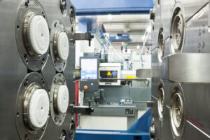
Klarm Mould Provides Precision Injection Molding

One normal technique for embodiment of fragile parts is pressure shaping as demonstrated in Fig. 13.6 for the creation of a tantalum capacitor. In this interaction, injection molding service china is set as a supplement between two layers of plastic 17 and 18 preceding the form conclusion. The shape configuration gives coordinating with pits 16 and 22 to get the plastic just as scores 21 to get the lead wires 20.

In any trim interaction, the form originator ought to expressly think about the treatment of the shaped parts upon de-embellishment. In the plan of Fig. 13.6, the lower cavity 22 is more profound than the upper depression 16. Furthermore, the lower shape half 11 is given a blaze well 23 for the assortment of any plastic that streams out of the depression during the pressure forming measure. Because of these plan components, the formed part will stay on the lower shape half when the mold opens.

In this pressure shaping interaction, the plastic layers 17 and 18 were cut from sheet stock in a structure to find a way into their comparing cavities while additionally supporting the capacitor 19 and lead wire, 20. It is attractive that the plastic completely contacts the back surface of the shape pits to work with heat move and plastic framing during china injection design service.

Preceding mold conclusion, cartridge radiators in the two form parts 10 and 11 bring the temperature of the shape and plastic layers to over the glass progress temperature of the plastic. When the plastic is mellowed, the shape is gradually shut with low power. As the form gradually shuts, the plastic gradually streams around the capacitor until it is completely epitomized – any abundance plastic in the hole will f1ow out the blaze surface, 24, and into the glimmer well, 23. When the embedded part is completely typified, full clasping power might be applied to the two form parts to make up for shrinkage and accomplish the ideal measurements while the shape is cooled.
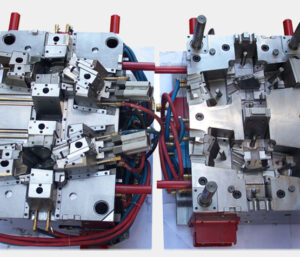
The shape plan of plastic precision injection mould factory has some interesting highlights. In the first place, the depressions secure the addition part in the form to stay away from undesired development brought about by the development of the shape or the progression of the plastic soften during the embellishment interaction. Second, this cycle was explicitly intended to give l0w weight on the embedded part by the controlled warming of the mold and relaxing of the plastic followed by the bracing and cooling of the shape. Given this warming and cooling cycle, the form ought to be painstakingly intended to limit the size and thickness of the plates s0 that energy utilization and process duration are limited. Third, this cycle utilized a lash surface and repository to control lashing of excess plastic; it is plainly attractive to choose a measure of plastic stock that limits the measure of lashing while at the same time guaranteeing a completely filled pit. In this plan, the mating lash surface, 24, on the lower form requires a moderately enormous leeway with mating surface on the upper shape half. In the event that this leeway is too little, the pace of the pressure shaping cycle can be restricted by the progression of the plastic dissolve out of the depression.

This is from https://www.injectionmouldchina.com/
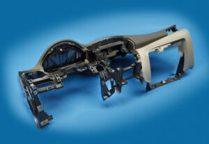
Klarm Mould Provides Competitive Molding Service

Attachment head cap screws are the most well-known latches utilized in molds. A %”13 attachment head cap screw is appeared in Fig. 12.32. The essential explanation is that attachment head cap screws have been deliberately planned [12] to enhance the exhibition of the head, strings, and fastener as a framework. In like manner, the attachment head cap screw gives a norm and efficient technique for holding numerous parts along the screw’s hub in injection mould tooling china.

The sizes and burden conveying capacity of attachment head cap screws are identified with their size, material, and medicines. Investigation of standard attachment head screw plans demonstrates that the head tallness is equivalent to the string width, and that the head distance across is around 150% of the string breadth. While the strength of the latch changes to some degree with the coarseness of the string, the rigidity of standard DIN/ISO screws can be genuinely very much assessed by accepting an extreme pressure, ultimate, of 800 MPa duplicated by the cross-sectional zone of the external string width.

Indicate the size of the attachment head cap screws used to secure the fixed and moving parts of the PC bezel mold. Since this attachment head cap screw is utilized in a basic application of high-precision mould china where disappointment may bring about loss of gear or life, a most dire outcome imaginable is expected.

To begin with, the most extreme mass of the form is assessed accepting a strong square of steel as indicated by the measurements gave in Fig. 12.7.

Then, the most dire outcome imaginable is expected. The most dire outcome imaginable happens when the shape is braced to just one side of the trim machine without the help of the moving platen, which may happen when the form is being introduced in the embellishment machine. Besides, the most dire outcome imaginable will expect that the whole mass of the shape should be upheld by just one fixed screw, which may happen if the other cap screws are not fixed or fixed to lesser sums. The subsequent burden case is appeared in Fig. 12.33.

The applied power on the screw by the form can be assessed by adding the minutes about the finding ring.

Cap screws ought not be depended upon to find form segments given their moderately huge spiral clearances. As recently examined, an obstruction fit ought to be utilized to find one part inside the pocket of another. For equal plates or stacked parts, in any case, dowels or other finding pins ought to be utilized as demonstrated in Fig. 12.34. In this plan, concentric openings are given into the coplanar surfaces of the two plates. A dowel at that point mates with the two openings to find the two parts along the pivot of the dowel.

Assembling differences in the openings’ area, width, and roundness limit the capacity to exactly find the two parts comparative with one another. Condition 12.28 can be utilized for different sorts of fits by fluctuating the cutoff cofficients, C, for the dowel and openings as per global guidelines. Table 1 2.2 gives Coefficients to a locational-leeway fit (LC1), locational-momentary fits (LT1 and LT3), just as the loosest locational-impedance fit (LN1). Locational freedom fits are planned for parts that are commonly fixed yet can be promptly dismantled and reassembled. This fit gives similar request of resistance as strung latches, so isn’t suggested for injection molds since the huge freedom can permit sped up wear of sliding surfaces. Locational-progress fits accommodate more tight control of area, yet with the chance of impedance between the dowel and the opening which upsets the shape get together.

This article is from https://www.injectionmouldchina.com

Klarm Mould Offers One-Stop Molding Services

The mold configuration should likewise incorporate clasp to inflexibly attach the numerous parts of the form. There are three sorts of latches generally utilized in molds while injection moulding china.

In the first place, fits are utilized by oem/odm industrial injection moulding design factory to firmly find one segment inside another, for example, a pit or center addition being situated inside a retainer plate. Second, finding pins or dowels are utilized by chinese injection moulding companies to find one parts over another, for example, the ejector lodging to the help plate. These initial two attaching strategies just give securing across the length and width headings of the mold. To attach the mold parts together in the tallness bearing, attachment head cap screws are utilized wherein the screw’s head is held in a form plate and the screw’s strings draw in the segment to be affixed. Every one of these attaching techniques is next broke down.

A”fit”refers to the mating of two segments. A leeway fit alludes to a mating where an ostensible freedom between the surfaces of the two segments. While a leeway fit furnishes for simple get together with insignificant inclusion powers, the freedom between the two segments allows the exact area of segments to stay obscure. Since tight resistances are needed in molds, impedance fits are normally used to find the mold segments.

Obstruction fits happen when the male segment has an ostensible measurement that is bigger than the ostensible element of the female segment, as demonstrated in injection moulding services for a center addition and a retainer plate. Since metals have a high versatile modulus, an inflexible obstruction fit can result when the distinction between the ostensible measurements is little, on the request for 0.01 % of the ostensible measurement. The snugness and inflexibility of the obstruction fit increments with the measure of impedance between the two segments. Sadly, the execution of obstruction fits is blocked by the dimensional varieties forced in the segments machining measures. Therefore, standard systems of fits have been created as far as possible on the elements of the segments.

The fits investigated here depend on a one-sided opening premise and have been changed over from U.S. standard units to metric units. Two of the most widely recognized principles for fitting include”Preferred Limits and Fits for Cylindrical Parts,” ANSI B4.1-1967 (R1999), and”Preferred Metric Limits and Fits” ANSI B4.2-1978 (R1999). ANSI B4.1 is investigated here because of its general straightforwardness and expansive materialness, however the mold originator may adjust to whatever standard is generally fitting. In this strategy, rectangular individuals with width, W, and length, L, are demonstrated as a roundabout part with clear distance across, D.

where C is a coefficient relating to the lower and furthest cutoff for the male or female segment given by worldwide norms. Table 12.1 gives coefficients to locational-obstruction fits (LN1 to LN3) and drive-impedance fits (FN1 to FN3). Locational-impedance fits are utilized when the exactness of area is basic and the parts require sidelong unbending nature. Be that as it may, locational-obstruction fits don’t give huge maintenance power in the stature course, so the parts should be gotten in the tallness heading to another segment through screws or different methods. FN1 to FN3 compare to drive fits with expanding impedance and requiring expanding addition powers. While drive fits give semi perpetual gatherings, mold plans for the most part give screws or different intends to decidedly holding the segments in the tallness heading.

This article is from https://www.injectionmouldchina.com/
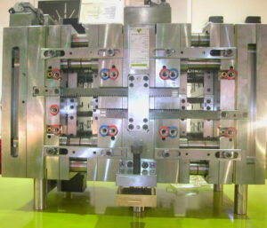
Klarm Mold Provides Qualified Injection Molding

Another basic issue with deep core is inordinate redirection or”core twisting” because of varieties in the soften pressure around the fringe of the center. The variety in liquefy pressure is regularly because of side gating as demonstrated in Fig. 12.27. Notwithstanding, slight varieties in dissolve stream can cause huge twisting in focus gated plans when the centers are thin (e. g., a center length on the request for multiple times the center breadth). The issue is compounded by the way that the core bending impact is self-supporting, which implies that a slight bending of the core encourages more soften stream and strain to the thicker part of the pit and further bowing of the core during injection moulding services china.

Center twisting can be investigated through fitting utilization of bowing conditions. Regularly, the center is held to the moving side of the mold, and the highest point of the center is allowed to twist.

The size of the pressing factor distinction around the center will shift with the calculation of the embellishment application. A more limited center, similar to that appeared in Fig. 12.27, will have a pressing factor contrast that is a critical part of the compel needed to fill the shape (maybe 50 % of the filling pressure). As the center turns out to be longer comparative with its distance across, the pressing factor contrast around the center will turn out to be less contrasted with the pressing factor distinction along its stature (maybe 10% of the filling pressure). Be that as it may, the center avoidance is relative to the fourth force of the center stature, so a little lopsidedness of the liquefy pressing factor can cause a huge redirection.

Normally, core bending in china industrial injection mold manufacturers turns out to be substantially more critical as the center turns out to be more slim. To limit center twisting, the form fashioner ought to use strong centers with an insignificant length to breadth proportion. Whenever the situation allows, slim center pins ought to be interlocked with the fixed side of the form as demonstrated in Fig. 1 2.28. Such interlocking of the center pin lessens the sidelong diversion of the pin to roughly 10% of the redirection for a pin that is upheld on just one end. When interlocking or expanding the size of the center is obliged by the math necessities of the trim application, the shape architect ought to emphatically suggest utilizing a middle entryway at the highest point of the corner or two contradicting doors at the lower part of the center to limit the pressing factor inclination applied on the center.

Figure 12.30 shows the utilization of stream pioneers by china injection mold maker as another way to deal with lessen the center redirection. In this plan, the stream chiefs will help the soften to go down the depression with lower filling pressures. Simultaneously, the dissolve will proliferate into the more slender neighboring segments of the pit and halfway freeze, subsequently keeping the center from avoiding a huge sum regardless of whether critical pressing factor contrasts emerge later in the filling stage. The stream chiefs appeared on the center in Fig.12.29 might be bothersome as bulges on the inward surface of the formed part, particularly for applications including contact with liquids. Thusly, the stream chiefs might be coordinated outwardly surface of the trim as per an assortment of plan arrangements set into the cavity embed. Obviously, center bowing can be extraordinarily decreased by utilizing various entryways on inverse sides of the center pin or by utilizing a ring door at the lower part of the center pin.

In some mold plans of injection mould manufacturers in china, the core is counterbalanced so then the soften is infused, the center pin avoids to deliver a uniform divider thickness. This idea is like providing”windage”to make up for warpage. The achievement of this system will rely upon the nature of the shape configuration, yet will stay touchy to changes in the plastic gum and handling conditions that influence the liquefy pressing factor and stacking on the center pin.

This article is from https://www.injectionmouldchina.com/