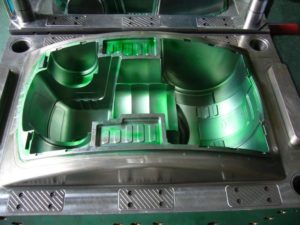
Klarm Mould Provides Competitive Molding Service

Attachment head cap screws are the most well-known latches utilized in molds. A %”13 attachment head cap screw is appeared in Fig. 12.32. The essential explanation is that attachment head cap screws have been deliberately planned [12] to enhance the exhibition of the head, strings, and fastener as a framework. In like manner, the attachment head cap screw gives a norm and efficient technique for holding numerous parts along the screw’s hub in injection mould tooling china.

The sizes and burden conveying capacity of attachment head cap screws are identified with their size, material, and medicines. Investigation of standard attachment head screw plans demonstrates that the head tallness is equivalent to the string width, and that the head distance across is around 150% of the string breadth. While the strength of the latch changes to some degree with the coarseness of the string, the rigidity of standard DIN/ISO screws can be genuinely very much assessed by accepting an extreme pressure, ultimate, of 800 MPa duplicated by the cross-sectional zone of the external string width.
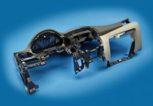
Indicate the size of the attachment head cap screws used to secure the fixed and moving parts of the PC bezel mold. Since this attachment head cap screw is utilized in a basic application of high-precision mould china where disappointment may bring about loss of gear or life, a most dire outcome imaginable is expected.

To begin with, the most extreme mass of the form is assessed accepting a strong square of steel as indicated by the measurements gave in Fig. 12.7.

Then, the most dire outcome imaginable is expected. The most dire outcome imaginable happens when the shape is braced to just one side of the trim machine without the help of the moving platen, which may happen when the form is being introduced in the embellishment machine. Besides, the most dire outcome imaginable will expect that the whole mass of the shape should be upheld by just one fixed screw, which may happen if the other cap screws are not fixed or fixed to lesser sums. The subsequent burden case is appeared in Fig. 12.33.

The applied power on the screw by the form can be assessed by adding the minutes about the finding ring.

Cap screws ought not be depended upon to find form segments given their moderately huge spiral clearances. As recently examined, an obstruction fit ought to be utilized to find one part inside the pocket of another. For equal plates or stacked parts, in any case, dowels or other finding pins ought to be utilized as demonstrated in Fig. 12.34. In this plan, concentric openings are given into the coplanar surfaces of the two plates. A dowel at that point mates with the two openings to find the two parts along the pivot of the dowel.

Assembling differences in the openings’ area, width, and roundness limit the capacity to exactly find the two parts comparative with one another. Condition 12.28 can be utilized for different sorts of fits by fluctuating the cutoff cofficients, C, for the dowel and openings as per global guidelines. Table 1 2.2 gives Coefficients to a locational-leeway fit (LC1), locational-momentary fits (LT1 and LT3), just as the loosest locational-impedance fit (LN1). Locational freedom fits are planned for parts that are commonly fixed yet can be promptly dismantled and reassembled. This fit gives similar request of resistance as strung latches, so isn’t suggested for injection molds since the huge freedom can permit sped up wear of sliding surfaces. Locational-progress fits accommodate more tight control of area, yet with the chance of impedance between the dowel and the opening which upsets the shape get together.

This article is from https://www.injectionmouldchina.com
Klarm Mold Provides Qualified Injection Molding

Another basic issue with deep core is inordinate redirection or”core twisting” because of varieties in the soften pressure around the fringe of the center. The variety in liquefy pressure is regularly because of side gating as demonstrated in Fig. 12.27. Notwithstanding, slight varieties in dissolve stream can cause huge twisting in focus gated plans when the centers are thin (e. g., a center length on the request for multiple times the center breadth). The issue is compounded by the way that the core bending impact is self-supporting, which implies that a slight bending of the core encourages more soften stream and strain to the thicker part of the pit and further bowing of the core during injection moulding services china.

Center twisting can be investigated through fitting utilization of bowing conditions. Regularly, the center is held to the moving side of the mold, and the highest point of the center is allowed to twist.

The size of the pressing factor distinction around the center will shift with the calculation of the embellishment application. A more limited center, similar to that appeared in Fig. 12.27, will have a pressing factor contrast that is a critical part of the compel needed to fill the shape (maybe 50 % of the filling pressure). As the center turns out to be longer comparative with its distance across, the pressing factor contrast around the center will turn out to be less contrasted with the pressing factor distinction along its stature (maybe 10% of the filling pressure). Be that as it may, the center avoidance is relative to the fourth force of the center stature, so a little lopsidedness of the liquefy pressing factor can cause a huge redirection.

Normally, core bending in china industrial injection mold manufacturers turns out to be substantially more critical as the center turns out to be more slim. To limit center twisting, the form fashioner ought to use strong centers with an insignificant length to breadth proportion. Whenever the situation allows, slim center pins ought to be interlocked with the fixed side of the form as demonstrated in Fig. 1 2.28. Such interlocking of the center pin lessens the sidelong diversion of the pin to roughly 10% of the redirection for a pin that is upheld on just one end. When interlocking or expanding the size of the center is obliged by the math necessities of the trim application, the shape architect ought to emphatically suggest utilizing a middle entryway at the highest point of the corner or two contradicting doors at the lower part of the center to limit the pressing factor inclination applied on the center.

Figure 12.30 shows the utilization of stream pioneers by china injection mold maker as another way to deal with lessen the center redirection. In this plan, the stream chiefs will help the soften to go down the depression with lower filling pressures. Simultaneously, the dissolve will proliferate into the more slender neighboring segments of the pit and halfway freeze, subsequently keeping the center from avoiding a huge sum regardless of whether critical pressing factor contrasts emerge later in the filling stage. The stream chiefs appeared on the center in Fig.12.29 might be bothersome as bulges on the inward surface of the formed part, particularly for applications including contact with liquids. Thusly, the stream chiefs might be coordinated outwardly surface of the trim as per an assortment of plan arrangements set into the cavity embed. Obviously, center bowing can be extraordinarily decreased by utilizing various entryways on inverse sides of the center pin or by utilizing a ring door at the lower part of the center pin.

In some mold plans of injection mould manufacturers in china, the core is counterbalanced so then the soften is infused, the center pin avoids to deliver a uniform divider thickness. This idea is like providing”windage”to make up for warpage. The achievement of this system will rely upon the nature of the shape configuration, yet will stay touchy to changes in the plastic gum and handling conditions that influence the liquefy pressing factor and stacking on the center pin.

This article is from https://www.injectionmouldchina.com/


Warpage Prediction

At the point when the embellishment comprises of a solitary shut zone, the material inside the trim is in constant contact with the end goal that any nonuniform shrinkage and stresses over the part may just be settled all through of plane twisting of the part. Injection mould manufacturers in china know that such warpage requires clasping of the plane of the part, which can happen when: (S edge一 S center)> 0.44. (h/W) (h/W)

where h is the divider thickness of the trim, and Scenter and Sedge are the shrinkage rates at the middle and edge of the part, and W is the good ways from the middle to the edge of the embellishment. This clasping examination models the embellishment as an isotropic roundabout plate under uniform outspread edge pressure with a clasping pressure limit of.

As the past warpage investigations have appeared, warpage is brought about by nonuniform shrinkage because of temperature inclinations through the divider thickness of the formed part, pressure angles over the territory of the shaped part, or temperature slopes aCross the zone of the shaped part. These are the most widely recognized reasons for warpage, and have been treated by high-precision mould china with the least complex conceivable examination. In any case, there are different reasons for nonuniform shrinkage including direction and remaining pressure. For additional data, the intrigued form fashioner is alluded to the examination writing.

Sensibly exact warpage forecasts may likewise be gotten with PC recreation as recently talked about. oem/odm largest plastic injection molding companies gives the warpage forecast from PC recreation for the reproduction portrayed for Fig. 10.8. The outcomes recommend that the center of the part will bow down while the left and right sides of the bezel will bow upwards. The purpose behind this conduct is the upper surface of the bezel contains more material, and this upper surface is contracting not exactly the lower part of the ribs.

Given that warpage can be huge contrasted with shrinkage, shape fashioners may decide to make up for warpage by invert biasing the form surfaces dependent on anticipated or noticed warpage. This predisposition is some of the time alluded to as “Kentucky windage,” a shooting term that alludes to the changes a separation shooter must make to represent the breeze [26]. In this manner, Kentucky windage in form configuration alludes to the shaping of the form cavity surfaces with the end goal that after twisting the formed part smoothes to the ideal shape. The utilization of such predisposition isn’t without discussion, since it acquires cost in the forming of shape cavity surfaces while likewise intrinsically changing the warpage and auxiliary conduct of the formed parts. Therefore, it stays a to some degree uncommon practice in oem/odm medical injection mold factory.

Break down warpage accepting that the cup top is focus gated and shaped with ABS at a pressing weight of 66 MPa at the focal point of the part and 0 MPa at the external edge. To assess the warpage, it is first important to compute the shrinkage rates and check the clasping basis. Given the 66 MPa pressing weight and a temperature of 132°C, the straight shrinkage at the middle will be 0.3 1% at the middle. At the edge, the weight of 0 MPa and temperature of 132°C gives a direct shrinkage of 1.66 %. Given that the cup is 2 mm in thickness and 81 mm in breadth, the clasping measure is expressed.

This article is from https://www.injectionmouldchina.com
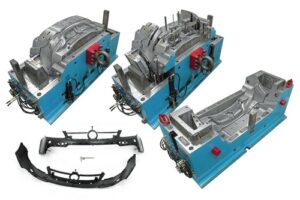
Shrinkage Prediction

PC reenactment is an undeniably basic in plastics item and form plan for china injection molded parts factory, with Autodesk/Moldflow, Core Iech/Moldex3D, and Sigma Engineering/Sigmasoft giving shrinkage assessment to shaped parts. To exhibit the examination for the bezel, Autodesk/Moldlow (Molding Plastics Insight, MPI 2014 [8]) was performed for Cycolac MG47. The isotropic shrinkage rates anticipated by the recreation are given in injection mold services china expecting similar conditions as the earlier investigation: a mid-range liquefy temperature, mid-range coolant temperature, a steady pressing weight of 66 MPa for a period of6 s, and a cooling season of 20 s.

The outcomes demonstrate that the shrinkage changes generally over the form hole. Low shrinkage rates (on the request for 0.3 % and underneath) are anticipated in the slight territories around the edge that freeze at high dissolve pressures. Specifically, the most minimal shrinkage of 0.1 % adjoining the door is anticipated as this region of the hole totally freezes at high soften pressures over 100 MPa while the polymer liquefy is filling the rest of the pit. Moderate shrinkage rates (around 0.6%) are anticipated in the majority of the part, which is more than the 0.31 % shrinkage recently anticipated by the manual investigation. High shrinkage rates (over 1 %) are anticipated close to the furthest limit of fill. The high shrinkage rate toward the finish of fill is because of the way that the material closer the entryway is hardening and forestalling extra polymer liquefy from arriving at the finish of stream to make up for volumetric shrinkage.

The outcomes show a critical issue for the shape planner and the end-client: what shrinkage worth ought to be utilized? In the event that a normal shrinkage of 0.6% is utilized, at that point the part width might be out of detail due to the exorbitant unaccounted shrinkage along the top and base edges.

There are a few unique procedures that can be utilized by the shape planner if nonuniform shrinkage happens. One progressively regular technique, which is upheld by the joint utilization of PC reproduction and CNC machining, is for the form planner to utilize distinctive shrinkage esteems in various parts of the shape. For the PC bezel appeared in oem/odm injection mould factory, the decay may pick a shrinkage estimation of 0.7% for the left and right sides and a shrinkage esteem over 1 % for the top and base sides. In this model, this procedure is moderately simple to utilize and would probably be fruitful since the calculation is generally straightforward. For more unpredictable item calculation with a firmly interconnected surface, in any case, the utilization of non-uniform shrinkage esteems can turn into an intricate and hazardous undertaking.

Another regular way to deal with acquiring tight resistances is to guarantee more uniform shrinkage over the form hole through the expansion of various entryways. By expanding the quantity of entryways for the PC bezel from two to four as appeared in china plastic injection molding, the filling and pressing weights and in this way the shrinkage rate are completely made more uniform over the form pit. In this model, the extra two entryways have diminished the greatest shrinkage from 1.3 % at the focal point of the top edge in Fig. 10.8 to 0.74% at the corners in high precision plastic injection mould factory. Besides, the normal shrinkage in the hole has been decreased from 0.7 % for the twogated shape plan to 0.65% for the four-gated form plan.

Coolant Flow Rate

When the cooling time is known to the china injection mold maker, the warmth move rate or”cooling power” expected of the feed system of the double coler mold parts can be determined. The aggregate sum of warmth to be eliminated by the cooling framework, Q mlingsg, is:

where mmoldings is the com bined mass of the formed parts and any related cold sprinters, which can be assessed as the volume of these moldings times their thickness at room temperature.

The cooling power is the characterized as the measure of energy that the must be eliminated every second of cooling time:

Normally, an injection mold has numerous cooling lines. Expecting that the mold is all around planned and each cooling line renoves a similar measure of warmth, at that point the warmth move rate per cooling line might be assessed as:

where nuines is the all out number of cooling lines in the shape. Now, the oem/odm largest plastic injection molding companies ought to perceive that various plan cycles might be important to play out the cooling investigation for various cooling line formats with shifting number of cooling lines.

Any warmth eliminated from the polymer dissolve in the shape hole must be diverted by the coolant. In that capacity, the coolant will increment in temperature as it goes through the shape. This temperature increment isn’t alluring, since the coolant will give less cooling to the last segment of the form through which it streams, If the coolant temperature increment is excessively incredible, at that point warm slopes will emerge over the shaped part, which may prompt differential shrinkage and warpage.

Given a volumetric stream pace of the coolant, V2o the expansion in the coolant

coolant’ temperature along one cooling line is:

The warm properties of some normal coolants are given by plastic mould manufacturers factory. The necessary coolant stream rate can be determined given the permissible increment in the coolant temperature. A commonplace permissible increment in the coolant temperature is 1°C. For an exactness forming application, the permissible increment in the coolant temperature might be 0.1°C. A lot more tight control of the coolant temperature requires a lot higher stream rates, but gives little included advantage given that the form hole surface temperatures will in general change all the more fundamentally between the cooling lines as later talked about.

Subsequent to assessing the necessary coolant stream rate, the plausibility of this worth ought to be checked against the abilities of business form temperature regulators. The determination for an ordinary coolant temperature regulator and an oil temperature regulator are recorded in oem/odm medical mold design factory.

The admissible scope of cooling line distances across would now be able to be resolved dependent on the warmth move and liquid stream limitations. To guarantee satisfactory warmth move from the shape steel to the coolant, tempestuous stream in the coolant is wanted. In the event that the cooling line width is excessively enormous, at that point the direct speed of the water may not be adequate to guarantee violent stream. To guarantee violent stream, the Reynolds number, Re, ought to be more prominent than 4000.

An additionally restricting imperative administers the base cooling line breadth, which is identified with the weight drop needed to compel the coolant through the cooling lines at the necessary volumetric stream rate, The weight drop for water through a cooling line can be assessed from pipe stream.

To figure the base cooling line measurement, the line length and passable weight drop over the cooling line must be known. This data can really be somewhat questionable, since it depends not just upon the design of the cooling lines in the shape, yet additionally whether the cooling lines are funneled in arrangement or equal.

This article is from https://www.injectionmouldchina.com
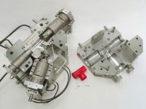
Feed System

The essential capacity of the feed system is to pass on the polymer dissolve from the nozzle of the trim machine (where it is plasticized) to the mold cavities (where it will frame an ideal item). In most embellishment applications, the polymer liquefy must cross segments of both the mold stature and the mold width. The crossing of the tallness and width can be practiced by two distinctive mold structures for the feed systems  of china injection mold maker. The feed system mold appeared at left CorreSponds to a two-plate cold sprinter mold structure. The sprue is utilized to manage the polymer soften from the nozzle of the trim machine to the splitting plane. Sprinters in the splitting plane are then used to direct the polymer soften aCIoss the splitting plane to at least one mold cavities.

The subsequent mold plan on the privilege of high-precision mould china relates to a three-plate or hot sprinter mold. In this subsequent structure, the polymer soften is guided over the width and length measurements of the mold by sprinters that are counterbalanced to the splitting plane. Since the sprinters are balanced from the splitting plane, there is huge structure opportunity concerning their directing and gating area. Nonetheless, two arrangements of sprues are required for the polymer soften to navigate the tallness of the mold. Initial, a sprue is expected to manage the polymer liquefy from the n0zzle of the trim machine to the plane of the parallel sprinters. After the soften fl0ws aCross the sprinters, a second arrangement of sprues is expected to direct the liquefy down through a bit of the mold stature to the mold cavities.

As the dissolve engenders through the feed system and cavities, the soften pressure in the infusion molding machine will increment. The feed system must be planned by injection mould manufacturers in china so that there is adequate liquefy strain to drive the polymer dissolve all through the mold cavities. A feed system with an enormous stream obstruction will cause a considerable weight drop during the trim cycle. The fIl0w pace of the polymer liquefy will start to rot when the trim machine arrives at the most extreme admissible injection pressure. On the off chance that the stream rate diminishes considerably before the finish of the mold documenting measure, at that point a short shot or different imperfections are probably going to happen.

The feed system must be intended to cause an adequate constrain drop to dodge short shots, broadened process durations, and different imperfections. The”acceptable” pressure drop through the feed system will rely upon the particulars of the embellishment application, particularly the liquefy constrain needed to fill the pit contrasted with the soften pressure accessible from the trim machine. For instance, a slim divider shaping application may utilize an embellishment machine with 200 MPa of accessible soften pressure. In the event that 150 MPa is needed to fill the depression, at that point the weight drop through the feed system ought not surpass 50 MPa. Nonetheless, if a similar machine was utilized to mold a section requiring just 100 MPa of weight, at that point the feed system could be intended to force a weight drop of 100 MPa.

To precisely indicate the adequate weight drop for the feed system structure by  oem/odm industrial injection moulding design factory, the mold planner should contact the decay to get the embellishment machine’s greatest infusion pressure. The mold fashioner ought to likewise get a gauge of the dissolve compel needed to fill the pit through examination, recreation, model embellishment, or related knowledge. In the event that this data isn’t known, at that point the mold fashioner can expect a most extreme weight drop through the feed arrangement of 50 Mpa (7200 psi). While this weight drop is marginally higher than some industry rehearses, this determination will bring about a steel-safe structure with littler feed system widths and lower material usage.

This article is from https://www.injectionmouldchina.com/

Injection Molding Runner Design in China

The Advantages Of Good Runner Designs To Help Injection Molding

The plastic injection molding process in China is possible because any thermoplastic material can be melted to a predetermined size and the Injection molding machinery is designed such that it can then be injected into a mold or cavity where it can be formed. The parts of the mold which are in the shape of the parts to be manufactured are the cavities. The formed part is then ejected from the injection mold.

The sprue is a part of the runner which injects molten liquid plastic material into the die or Chinese mold through the injection machine’s nozzle. The runner system, as well as the sprue, is the passage that connects the nozzle of the machine to the mold cavities. Runner connects the sprue with the cavity through the gate.  The nozzle of the machine is connected to the runner by the sprue and come in designs of hot sprue or cold sprue.

Injection Molding Runner Design in China

The Injection molding runner design comes in three basic types – hot runner, insulated runner, and cold runner. The runner has to ensure that the liquid material is distributed so that it fills all the China molds under the same conditions and the same pressure at the same time. This will help to prevent flashing of the china injection mold and also helps in producing parts of a uniform and improved quality. Hot runner technology, which is externally heated is more practical and feasible since the plastic is maintained in a liquid state and most China mold makers use this technology.

The usage of hot runners in injection molding machinery is useful since it ensures better quality parts. They are particularly beneficial with uneven-shaped parts which might result in improper cooling or uneven flow. Hot runners also help in reducing plastic wastage.  They are designed to reduce cycle time, thus helping to maximize manufacturing productivity. The challenge in design is to maintain the liquid plastic which is molten at an optimum temperature while the china injection mold cavity is being cooled at the same time. Internal as well as external heating methods are used generally in injection molding machinery. Thus the hot runner technology, which was introduced almost 50 years before in the plastic industry, has revolutionized the china plastic injection molding technology and its processing capabilities by enhancing the efficiency of operation, improving the quality of the parts, reducing wastage and scrap and thus in effect saving money.

A very critical consideration for injection molding runner design as well as the china injection molding process is to maintain a uniform temperature in the hot-runner manifold and the sprue bar so as to ensure consistency in quality. Another consideration to be taken by China mold manufacturers is regarding the runner system. The injection mold china cavities will not be filled properly if the runner is too small. If the runner is too large, then cooling time will be increased and the cycle time will be decreased. Proper design for runners for injection molding china is most essential to reduce the effect of sink, stress, and weld marks.

A good and efficient runner design is most essential for plastic injection molding machinery as it helps in producing better quality parts at a very reasonable and affordable rate due to higher efficiency and lower wastage. Currently there are many suppliers who provide injection molding systems from China at very good quality.

Resource box: This article is originally posted in https://www.injectionmouldchina.com.

Banana Gate Injection Molding in China

Key points to Banana Gate Injection Molding

Manufacturing is a simple business of making goods by hand or by a machine. Once the goods are made, they are sold to a customer. There are several different types of manufacturing processes in this world. China Injection Molding is one of them.

Banana Gate Injection Molding in China


What is Injection Molding & an Injection Molding Machine?

Injection Molding is one of the most commonly used manufacturing procedures for the production of plastic parts. As it is used for the molding of plastic, it is also known as plastic injection molding. Different types of products are produced using an injection molding technique – plastic trinkets, automotive parts, toys, mobile cases, bottles & containers.  Injection molding is done with the help of an injection molding machine, raw materials & mold. This process consists of 3 valuable steps – designing of product, designing of mold & the manufacturing process. The injection molding machinery uses a melt, inject, cool & pack procedure by converting granules of raw plastic into final molds.

Injection mold design is an important factor in the China plastic injection molding machine & each injection design consists of a gate to allow the melted plastic flow to be injected into the cavity of the Chinese mold. Different issues may arise if the wrong scale of the gate is chosen like uncompleted filling, molding shrinkage & excessive residual stress. There are two types of gates for injection molding machines-one is manually trimmed & the other one is an automatically trimmed gate. Under these two categories, there are 9 different gates called Direct Spruce Gate, Side Gate, Fan Gate, Pinpoint Gate, Disk Gate, Rin Gate, Film Gate, Tab Gate & Submarine Gate. Depending on the part of the design, the gate can be small or large. The location of the gate is also important in the manufacturing process as it decides how the plastic will enter & form into a mold.

China is one of the major producers of plastic injection molding. China mold makers have made notable progress in the last few years in the business of China injection molding. Companies from around the world come to this country with the wrong expectations of purchasing cheap China mold. To avoid delivery fraud, it is better to look for manufacturers around your location. This will also save delivery time.

Banana Gate Injection Molding

This type of molding machine uses the banana gate for its production. The banana gate is similar to the tunnel or submarine gate & it is curved like a banana. This is a new type of gate which is quite trendy in the China plastic injection molding machines. These gates are very useful as they do not leave any marks on the plastic surface. Because of its magnificent curvy shape, it can reach below the part & allows the plastic to be injected into the secluded area of the part. Banana gate injection molding is normally used for ABS & HIPS materials. If these types of gates are not properly designed, then the machine can break easily.

China injection molding is a standard process for manufacturing plastic involving raw materials & molds. It is one of the most cost-efficient manufacturing processes. Injection mold machinery is capable of producing high volumes of high-quality plastic.

Resource box: This article is originally posted in https://www.injectionmouldchina.com.

gas assisted injection mold in China

How to make gas assisted injection mold?

The gas-assisted injection molding is a process that involves the traditional, low-pressure process of injection molding. This process uses pressurized nitrogen gas to force material into a mold. Let’s find out more about gas-assisted injection molding.

gas assisted injection mold in China

Basically, this process is used to produce big parts of plastic using complex designs and beautiful surface finishes. Normally, this process is a great choice for making skins, cabinets, bezels, doors, equipment covers, and handles.

Internal Injection Molding

As said earlier, this process injects pressurized nitrogen gas into a mold. Actually the nitrogen gas is passed through the gas channels for displacing the material through the creation of hollow sections.

The molten resin is pushed against the wall of the cavity until the solidification of the path. The constant pressure of the gas prevents the shrinkage of the part. In addition, it reduces internal factors, sink marks, and surface blemishes. So, this process can work well to hold curvatures and tight dimensions.

External Injection Molding

In this type of injection molding, the material is pushed into the mold. However, the gas is pushed in a very thin layer between the mold core and the back surface of the component. So the front surface of the component is forced against the other side of the cavity of the mold. as the gas cools down, different sides of the component replicate the mold surface.

Basically, this process is suitable for plastic parts that feature large surface areas, especially those parts that require beautiful surface and detailed textures. In this process, the sink and warp marks are removed because in nitrogen gas maintains the material condition.

Just like internal gas assist, the bosses and support ribs are molded into the component and produce the same level of tolerance and dimensional stability. In the same way, molding pressure produces less stress wear and tear.

Cost Considerations

This process also helps save a lot of money. Typically, these processes require a lot less force than traditional injection molding. Therefor it helps reduce the component chords costs and produces less stress as well.

Actually, the mold pressure results in reduced wear and tear. Therefore, there would be less demand for pricey aluminum tooling. Moreover, the parts made are lightweight which will help reduce the freight expenses and boost material handling.

Design Benefits

Moreover, this technology results in a lot of performance and design benefits. For example, multiple parts with different thickness off walls can be molded.

Converting different components to Gas Assist

This type of injection molding is a better alternative to the large metal parts. Therefore, it is possible to eliminate expensive, heavyweight, corrosive components like panels, access doors, enclosures hand covers.

In short, this was a brief introduction to gas-assisted injection molding. Hopefully, this article will help you understand the concept much better.

Resource box: This article is originally posted in https://www.injectionmouldchina.com.

injection molding defects

How to eliminate injection molding defects?

Injection molding is an art, which involves science as well. Actually, injection molding requires great attention to detail as minor mistakes can cause a lot of financial loss to a company. In this article, we are going to discuss how you can eliminate common injection molding defects.

injection molding defects

Flow Lines

Flow lines may include lines, patterns, and streaks that appear on the prototype part because of the cooling profile or physical path of the molten plastic while it moves into the cavity.

Fix:

  • One way to fix the issue is to increase the pressure and injection speed, which will make sure that the mold will fill the cavities.
  • Another way is to round the locations and corners where the thickness of the wall changes.

Sink Marks

These are minor depressions or craters that form in the thicker areas when shrinkage happens in the internal areas of the end product.

Fix:

  • Reduce the mold temperature, increase the holding pressure and time for better curing and cooling.
  • Reduce the thickness of the wall sections that are the thickest. This will allow faster cooling and prevent the sink marks.

Vacuum Voids

Vacuum voids refer to the air pockets inside or near the prototype surface. They occur because of the uneven solidification amidst the inner sections and the surface.

Fix:

  • Find the gate at the mold’s thickest part
  • Opt for the plastic that is less viscous, which will reduce the amount of gas trapped.
  • Increase the holding time and pressure
  • Try to keep the mold parts aligned

Surface Delamination

Surface delamination happens when thin layers of the surface show up on the part because of a contaminant. Actually, these layers look like coats that can be peeled off.

Fix:

  • Before molding, make sure you dry the plastic properly
  • Raise the degree of mold temperature
  • There should no sharp turns and corners in the mold design

Weld Lines

Weld lines show up on an area where the liquid plastics mixes while they flow from different injection mold parts.

Fix

  • Increase the temperature of molten plastic or mold
  • Raise the injection speed
  • Make adjustments to the design to ensure that the flow pattern is only one source flow

Short Shot

Short shot refers to a situation that happens when a molding shot tends to fall short. In other words, the molten plastic won’t fill the cavity of the mold for some reason. As a result, it leaves a portion where you can see plastic.

Fix

  • Opt for a plastic that features higher flow and less viscosity
  • Raise the mold temperature for better flow
  • Get a machine that features more material feed

To cut a long story short, you may have to face a lot of defects during the process of injection molding in China. What you need to do is follow the tips given in this article to fix or eliminate these issues to make the process error free. Hopefully, you will find these tips helpful.

Resource box: This article is originally posted in https://www.injectionmouldchina.com.