Mold Layout Design

When the heap cases are created for superposition, the recently introduced pressure and bowing examinations might be performed to gauge the pressure in the help column, σ, the avoidance because of pressure, oppression; and the redirection because of bowing, bending. The avoidance across the outside of the mold hole can be assessed as an element of the distance, x, from the centerline of the help column. Where L is the length of the range from the help column to the ejector rail and the scope of x is confined to one a large portion of the length of the range.

The greatest avoidance of the mold will happen either at the focal point of the help column or somewhere between the help column and the ejector rail, contingent upon the general sizes of the redirections. This prompts the accompanying equation for the most extreme avoidance given the superimposed pressure and twisting.

The mold creator ought to consistently consider the conveyance of the powers applied by the polymer liquefy in the cavity to decide the area and size of the help columns. Consistently dispersed help columns might be adequate, yet are once in a while ideal, Often, it is valuable for high-precision mould manufactory to break down the mold into discrete regions for primary investigation and plan.
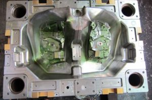
injection mold gate design

The underlying conduct of every 50% of the mold for eight depressions could be examined with a range of 359 mm and a width of 178 mm. The foundational layout may incorporate two huge help columns under each gathering of four cavities as appeared at left, or six more modest help columns separated between sets of depressions as appeared at right. The mold fashioner could likewise consider one help column straightforwardly under every pit. Every one of these plans can be examined. The last plan will be resolved by the underlying exhibition, yet in addition the discharge and upkeep contemplation. Once more, the easiest and most conservative plan is generally liked.

The mold format plan of oem injection mold factory is remarkable for two different reasons. In the first place, this plan shows 16 center additions pressed straightforwardly in a 4×4 matrix in one enormous pocket in the center plate with no interceding mold steel. This plan is substantially more smaller and less expensive to deliver than a plan with 16 individual pockets for the center supplements. Be that as it may, the plan will require cautious machining, completing, and get together of the mold embeds since resilience issues can cause positional mistakes and issues during trim, for example, coolant spills, blazing at the splitting line, or out of resistance molded parts. Second, the plan of china precision molds factory is a family mold in which each set of eight holes is molded with various thicknesses and at various liquefy pressures. Planning the hot sprinter feed framework would be testing. A stacked “X” type complex like the plan of plastic injection molding services china could be utilized with various measurements for the essential sprinters to adjust the dissolve pressures during filling.

Be that as it may, given the distinctive part thicknesses and comparative pressing weights gave to all the holes, the mold originator ought to anticipate less shrinkage in the more slender top moldings and specified a lower shrinkage esteem as needs be.

The portrayed investigation techniques give sensible direction to mold plan. On the other hand, primary recreations of injection mould manufacturers utilizing limited component investigation can be performed utilizing the point by point mold math. Such primary examination procedures are getting progressively coordinated with PC stream recreations to give high-devotion forecasts while likewise decreasing huge hindrances to routine usage.

This article is from https://www.injectionmouldchina.com
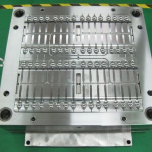
Cooling Line Pitch

When the cooling line profundity is chosen, the separation between the cooling lines (known as the”pitch”) is appointed. A more tight pitch, Wine, between cooling lines accommodates quicker and more uniform cooling. Nonetheless, a more tight pitch likewise implies all the more cooling lines and the probability of contentions emerging between the cooling lines and other shape segments. The mold architect from injection mould manufacturers should choose a cooling line pitch that is fitting for the spec ific shaping application utilizing examination.

The temperature expectation of the liquefy during cooling includes the arrangement of an arrangement of illustrative differential conditions. While this is promptly comprehended utilizing the limited component strategy as over, no reasonable systematic treatment has yet been created. This capacity is plotted in newest double coler mold parts for steel and an aluminum form materials. The examination shows that the variety in the warmth transition is under 5% up to a cooling line pitch equivalent to double the cooling line profundity. Thereafter, the variety in heat motion increments significantly and is characteristic of more slow paces of shape cooling and high temperature angles inside the formed part.

To stay away from a critical temperature angle between cooling lines, it is suggested that form planners utilize a cooling line contribute the scope of relying upon the necessities of the application. An item with free resiliences would probably approve of a cooling line pitch equivalent to a few times the cooling line profundity. For more tight resistance applications or for applications requiring quicker process durations or more uniform cooling, a closer separating equivalent to the cooling line profundity is alluring.

Figure 9.5 shows that the utilization of profoundly conductive materials, (for example, aluminum or copper) really expands the variety in heat motion by improving the warmth conduction between the cooling line and the cavity surface. All things considered, the utilization of profoundly conductive materials doesn’t legitimately take into consideration a more extensive pitch and a diminished number of cooling lines. On the off chance that less cooling lines are wanted, at that point this may best be cultivated by choosing a huge cooling line profundity and as yet setting the pitch to twice this sum. Exceptionally conductive form materials would then be able to be used to achieve high paces of warmth move with uniform cooling.

Transient warm recreation was performed for the cup/cover family shape for two form plans having diverse pitch to cooling line profundity proportions. China standard components for injection mold plots the warmth stream from the centerline of the embellishment in the pit to the cooling. In the figure, the lengths of the bolts speak to the overall measure of warmth streaming out of the form depression at that area. As the cooling lines are moved further separated two unfavorable conditions emerge. To start with, the compelling warmth move rate at the form divider is diminished given the limited limit of the cooling lines to eliminate heat. Second, a critical variety in the warmth move rate emerges over the cavity surface.

This variety in the warmth move rate over the hole surface will offer ascent to a slope in the temperature of the moldings at the hour of launch as plotted in oem/odm automatives injection molding design factory. With a tight cooling line pitch, the moldings are catapulted not just with a lesser temperature variety over the trim, yet in addition at an essentially lower temperature. With a wide pitch, the moldings display an a lot higher temperature inclination and an a lot higher temperature.  Curiously, expanding the process duration for the form with the more extensive pitch doesn’t decrease the temperature angles without fundamentally expanding the cooling time to permit the whole shaped part to move toward the coolant temperature.

This article is from https://www.injectionmouldchina.com
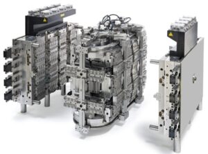
Sucker Pin in Mode Design

Three-plate mold designs from china industrial injection moulding suppliers, frequently use sprue pullers, or”sucker pins,”to follow the chilly runner system to the stripper plate upon the launch of the mold. In this example of injection mold service china, the utilization of sucker pins is expected to give adequate ductile power along the sprue with the end goal that exorbitant pliable anxieties break the door between the sprue and trim. Without the sucker sticks, the chilly runner system would go with the depression plates and be hard to eliminate, since the entryways would even now be joined and there is no instrument given on the a plate to discharge the runner system.

Likewise, mold architects from injection mould manufacturers ought to consider the need of sucker pins during the design of two-plate molds. The essential concern is that the cool runner system may stick to the A portion of the form due to either vacuum attractions to the A plate surface or to the hardening of the plastic dissolve to the machine spout at the head of the sprue. On the off chance that the chilly runner system remains with the fixed side of the mold and all the discharge instruments are on the moving side of the form, at that point the runner system can’t be consequently launched out. The embellishment machine administrator will probably need to postpone the trim machine to physically eliminate the runner system. Besides, in the event that the machine is working on a programmed cycle, at that point the trim machine may attempt to close the form with the runner system still in the mold.

To dodge these issues and improve the dependability of the trim activity, sucker pins might be put at different areas along the feed framework. Maybe the most significant sucker pin is the sprue puller, situated at the base of the sprue, which most successfully serves to disengage the sprue from the machine spout and hold the sprue with the moving side of the mold. In this design by china industrial injection moulding manufacturers, the converse mold at the base of the sprue causes an undercut that holds the sprue. This undercut is later sheared off with the forward actuation of the sprue take out pin.

Other sucker pins might be put at different areas along the cool runner system and, if essential, in the mold pits. The design is very like that of the sprue puller. As for the design, it is re-compacted that the breadth of the sucker be somewhat not exactly the distance across of the related sprinter to keep away from expanded cooling times. The stature and tighten edge of the sucker pin ought to be adequate to pull the sprinter off the fixed side of the form without unnecessary material use Or causing clasping of the related ejector pins upon forward actuation. Common statures and tighten points are one a large portion of the sprinter width and 5 degrees, separately.

The usage justifies a concise conversation. In this usage, an ejector pin has been put underneath the sprinter and opened with a converse mold to hold the sprinter until discharge. Contrasted and the implementation gave at right, the utilization of the opened ejector is a lot more straightforward to machine and simpler to keep up. There are two basic issues, notwithstanding. When high precision plastic making mould suppliers china to start with, the pin as indicated distends marginally into the sprinter area. While this projection won’t fundamentally adjust the stream rates or weight drop through the sprinter, there is a slight possibility that it might incidentally cause an undesired interruption or flimsiness in the stream front. Consequently, it is wanted to adjust the head of the ejector pin with the base of the sprinter. Second, if numerous opened ejector pins are utilized to hold and discharge the runner system, at that point the form fashioner should consider the overall arrangement of the undermining openings. In the event that the arrangement of the openings are not controlled and given aimlessly points, at that point the runner system may accidentally tie to the sucker pins at launch in an arbitrary manner, hampering the appropriation of a fully programmed shaping cycle.

This article is from https://www.injectionmouldchina.com