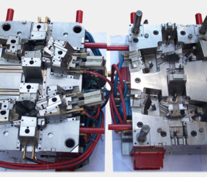
Most of the mold comprises of plates, including the top clasp plate, A plate, cavity embeds, center additions, B plate, uphold plate, ejector plate, ejector retainer plate, and the back clip plate. A prominent exemption is the plan of molds with profound centers, wherein the center supplement isn’t built from a plate yet rather from a pole; this sort of form configuration has a different arrangement of issues that are along these lines examined by china high precision injection molding machine.
Every one of the mold plates is regularly exposed to a heap on one face of the plate. While the sides of the plate might be obliged by encompassing plates, most of the applied burden is conveyed by compressive and shear stresses and consequently sent through the thickness and across the plate. Plate pressure and bowing are next independently examined.
In the event that the plate is completely upheld by basic mold plates and the form platen (as common on the fixed side of the form), at that point all plates are in pressure and there is irrelevant plate twisting. It ought to be noticed that compressive powers because of mold bracing will in general reason uniform compressive burdens through the form plates. The compressive pressure, σ, is characterized as the power, F, per unit of compacted territory, Acompression: σ=F/Acompression The strain, e, that creates is the pressure isolated by the versatile modulus, E: e=σ/E
Diversion because of pressure isn’t generally an issue since 1) it is moderately little and 2) it is uniform across the form. In that capacity, it doesn’t ordinarily cause blazing or huge dimensional change in the chinese mold component machining manufacturers. As the accompanying model will show, in any case, the mold planner ought to marginally expand the profundity of the form pit to make up for plate pressure if a tight resistance is determined on the thickness of a section with a profound hole.

In the event that the back essence of the plate isn’t completely upheld, at that point shear stresses will create and Cause the plate to twist, Plate bowing is a normal issue for the plates situated between the ejector lodging and the form depression 0n the moving side of the mold. The shear pressure, T, is characterized as the power, F, per unit of zone in shear, Ashear: T=F/Ashear
China high precision mold manufacturer Guangzhou Klarm Mould Limited gives an illustration of a static power examination of a part of the bezel form that is in shear, While the genuine shear stresses will shift with the appropriation of the liquefy pressure across the mold depression, a sensible gauge can be accomplished by expecting a uniform circulation around the border of the mold hole. In that capacity, the region in shear is: The key issue with plate twisting in mold configuration isn’t the presence of shear stresses in the plates, yet rather the improvement of enormous redirections across any long unsupported ranges of the form plates. Most mold use a moving ejector get together, thus don’t completely uphold the help plate between rails of the ejector lodging. Likewise, the mold plates act like a pillar in bowing. The glorified case is spoken to in china molds produce services in which the whole burden, F, is thought to be applied to the focal point of the mold area. This supposition that is made to give a traditionalist gauge of the most extreme redirection.
As for different depression mold, the examination ought to be applied to isolate bits of the form cavity as suitable. china injection mold factory gives a top and side perspective on a format plan for a six-pit mold. One investigation approach is to lump the liquefy pressure across three holes together to register the applied power, F, which acts fundamentally on the compelling width, W. It ought to likewise be noticed that the powerful plate thickness, H, ought exclude the thickness of the centers when the centers don’t contribute altogether to the solidness of the form get together.
This article is from https://www.injectionmouldchina.com
