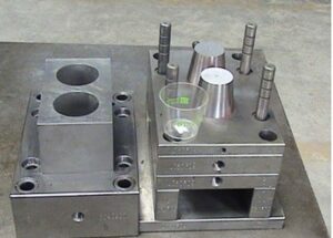
Mold Layout Design

When the heap cases are created for superposition, the recently introduced pressure and bowing examinations might be performed to gauge the pressure in the help column, σ, the avoidance because of pressure, oppression; and the redirection because of bowing, bending. The avoidance across the outside of the mold hole can be assessed as an element of the distance, x, from the centerline of the help column. Where L is the length of the range from the help column to the ejector rail and the scope of x is confined to one a large portion of the length of the range.

The greatest avoidance of the mold will happen either at the focal point of the help column or somewhere between the help column and the ejector rail, contingent upon the general sizes of the redirections. This prompts the accompanying equation for the most extreme avoidance given the superimposed pressure and twisting.

The mold creator ought to consistently consider the conveyance of the powers applied by the polymer liquefy in the cavity to decide the area and size of the help columns. Consistently dispersed help columns might be adequate, yet are once in a while ideal, Often, it is valuable for high-precision mould manufactory to break down the mold into discrete regions for primary investigation and plan.
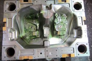
injection mold gate design

The underlying conduct of every 50% of the mold for eight depressions could be examined with a range of 359 mm and a width of 178 mm. The foundational layout may incorporate two huge help columns under each gathering of four cavities as appeared at left, or six more modest help columns separated between sets of depressions as appeared at right. The mold fashioner could likewise consider one help column straightforwardly under every pit. Every one of these plans can be examined. The last plan will be resolved by the underlying exhibition, yet in addition the discharge and upkeep contemplation. Once more, the easiest and most conservative plan is generally liked.

The mold format plan of oem injection mold factory is remarkable for two different reasons. In the first place, this plan shows 16 center additions pressed straightforwardly in a 4×4 matrix in one enormous pocket in the center plate with no interceding mold steel. This plan is substantially more smaller and less expensive to deliver than a plan with 16 individual pockets for the center supplements. Be that as it may, the plan will require cautious machining, completing, and get together of the mold embeds since resilience issues can cause positional mistakes and issues during trim, for example, coolant spills, blazing at the splitting line, or out of resistance molded parts. Second, the plan of china precision molds factory is a family mold in which each set of eight holes is molded with various thicknesses and at various liquefy pressures. Planning the hot sprinter feed framework would be testing. A stacked “X” type complex like the plan of plastic injection molding services china could be utilized with various measurements for the essential sprinters to adjust the dissolve pressures during filling.

Be that as it may, given the distinctive part thicknesses and comparative pressing weights gave to all the holes, the mold originator ought to anticipate less shrinkage in the more slender top moldings and specified a lower shrinkage esteem as needs be.

The portrayed investigation techniques give sensible direction to mold plan. On the other hand, primary recreations of injection mould manufacturers utilizing limited component investigation can be performed utilizing the point by point mold math. Such primary examination procedures are getting progressively coordinated with PC stream recreations to give high-devotion forecasts while likewise decreasing huge hindrances to routine usage.

This article is from https://www.injectionmouldchina.com
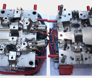
Mold Plates Compression and Bending

Most of the mold comprises of plates, including the top clasp plate, A plate, cavity embeds, center additions, B plate, uphold plate, ejector plate, ejector retainer plate, and the back clip plate. A prominent exemption is the plan of molds with profound centers, wherein the center supplement isn’t built from a plate yet rather from a pole; this sort of form configuration has a different arrangement of issues that are along these lines examined by china high precision injection molding machine.

Every one of the mold plates is regularly exposed to a heap on one face of the plate. While the sides of the plate might be obliged by encompassing plates, most of the applied burden is conveyed by compressive and shear stresses and consequently sent through the thickness and across the plate. Plate pressure and bowing are next independently examined.

In the event that the plate is completely upheld by basic mold plates and the form platen (as common on the fixed side of the form), at that point all plates are in pressure and there is irrelevant plate twisting. It ought to be noticed that compressive powers because of mold bracing will in general reason uniform compressive burdens through the form plates. The compressive pressure, σ, is characterized as the power, F, per unit of compacted territory, Acompression: σ=F/Acompression The strain, e, that creates is the pressure isolated by the versatile modulus, E: e=σ/E

Diversion because of pressure isn’t generally an issue since 1) it is moderately little and 2) it is uniform across the form. In that capacity, it doesn’t ordinarily cause blazing or huge dimensional change in the chinese mold component machining manufacturers. As the accompanying model will show, in any case, the mold planner ought to marginally expand the profundity of the form pit to make up for plate pressure if a tight resistance is determined on the thickness of a section with a profound hole.

In the event that the back essence of the plate isn’t completely upheld, at that point shear stresses will create and Cause the plate to twist, Plate bowing is a normal issue for the plates situated between the ejector lodging and the form depression 0n the moving side of the mold. The shear pressure, T, is characterized as the power, F, per unit of zone in shear, Ashear: T=F/Ashear

China high precision mold manufacturer  Guangzhou Klarm Mould Limited gives an illustration of a static power examination of a part of the bezel form that is in shear, While the genuine shear stresses will shift with the appropriation of the liquefy pressure across the mold depression, a sensible gauge can be accomplished by expecting a uniform circulation around the border of the mold hole. In that capacity, the region in shear is: The key issue with plate twisting in mold configuration isn’t the presence of shear stresses in the plates, yet rather the improvement of enormous redirections across any long unsupported ranges of the form plates. Most mold use a moving ejector get together, thus don’t completely uphold the help plate between rails of the ejector lodging. Likewise, the mold plates act like a pillar in bowing. The glorified case is spoken to in china molds produce services in which the whole burden, F, is thought to be applied to the focal point of the mold area. This supposition that is made to give a traditionalist gauge of the most extreme redirection.

As for different depression mold, the examination ought to be applied to isolate bits of the form cavity as suitable. china injection mold factory gives a top and side perspective on a format plan for a six-pit mold. One investigation approach is to lump the liquefy pressure across three holes together to register the applied power, F, which acts fundamentally on the compelling width, W. It ought to likewise be noticed that the powerful plate thickness, H, ought exclude the thickness of the centers when the centers don’t contribute altogether to the solidness of the form get together.

This article is from https://www.injectionmouldchina.com
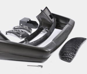
Ejector Gathering

While strung take out poles are moderately easy to plan and work, some shape producers and disintegrates use pressure springs to restore the ejector gathering preceding mold conclusion. One plan is appeared in china automotives injection mold manufacturers, which utilizes a few pressure springs situated between the help plate and the ejector retainer plate.

At the point when the take out bar incites the ejector gathering, the springs are put in pressure. At the point when the trim machine withdraws the take out rod(s), the pressure springs will in general reset the ejector get together. A couple of notes on the plan of pressure springs are justified by china high precision injection molding machine factory. Initial, a help pin should be utilized in the focal point of the pressure spring to abstain from spring clasping when the free length of the spring surpasses multiple times the breadth of the spring; the help pin should be strung into the help plate or back cinch plate to find the spring.

Second, the scope of spring pressure should be restricted to about 40% of the free length of the spring. The distance across and check of the spring should be chosen to give a return power that is a portion (for instance, one-fourth) of the necessary discharge power.

Both these early return frameworks are normal, yet the positive get back with strung take out poles gives a few preferences. To begin with, positive return gives criticism to the trim machine about the situation of the ejector framework.

Second, the positive return framework requires less changes to the form plan. Third, the pressure springs limit the scope of ejector travel and can be harmed or cause harm if the trim machine powers the ejector get together past the pressure spring’s scope of free travel. Fourth, pressure springs and ejector frameworks will in general wear to such an extent that molds with pressure springs often neglect to totally restore the ejector framework after an inconclusive number of embellishment cycles. In one or the other case, if early return of the ejectors should be ensured before shape conclusion, at that point the form fashioner ought to incorporate a cutoff switch that is dynamic when the ejector framework is completely reset.

There are numerous kinds of ejection parts as the broke down and planned by high precision mold factory in the earlier segments. There many particular discharge framework plans that have been created to give shaped parts complex outside subtleties, complex inside subtleties, a tasteful surface totally liberated from surrenders, and different purposes. A portion of the generally basic discharge frameworks are next talked about.

As talked about china molds design services, center pulls and sliding additions are usually utilized when there is at least one outside undermines. In the event that the segment of the hole with undermines is exceptionally huge, or if the outside of the formed part requires a splitting plane that is cross over to the shape opening bearing, at that point a split hole shape is frequently planned. As the term”split cavity”implies, a split depression form is a shape plan in which the hole embed is part into at least two pieces, with the end goal that the dividers of the pit can be moved away from the formed part during the discharge phase of the embellishment cycle.

This article is from https://www.injectionmouldchina.com/

Ejection Force

When the necessary push territory and edge of the ejectors are known, distinctive ejector frameworks plans can be created. The form creator ought to think about various plans with a differing number and sizes of ejectors. There are preferences and hindrances to ejector framework plan methodologies having an enormous amount of little ejector pins contrasted with having less yet bigger ejector pins. As for tooling and activity costs, fewer huge ejector pins are liked by chinese mold component machining manufacturers.

There are two essential reasons. Initial, fewer ejectors requires a lower number of form segments and highlights to be machined. Consequently, the shape is more affordable to produce and keep up. Then, the bigger size of the ejectors will in general have exceptionally low compressive burdens and in this way be less defenseless to clasping.

Concerning plan flexibility and form activity, notwithstanding, a bigger number of little ejector pins is liked in high precision mold factory. There are a few reasons. To start with, the more noteworthy number of ejector pins considers more regular position of the ejectors over the pit.

This higher thickness of ejectors will in general accommodate more uniform venting and discharge. Simultaneously, more modest estimated ejectors permit more noteworthy plan adaptability as for the position of the ejectors. As recently talked about, molds contain numerous firmly dispersed and complex highlights so little ejector sizes permits pins to be viably positioned between cooling lines, down thin centers, on side dividers or ribs, and so forth

The mold planner from china precision molds manufacturers ought to recall that the above examination just gives a lower cutoff to the number and size of the ejectors. The shape architect can generally add ejectors or increment the ejector size to improve the consistency of discharge or lessen pressure in the formed part. The shape planner should likewise decide the sort of ejector to be utilized at different areas. Normal parts incorporate ejector pins, ejector edges, ejector sleeves, stripper plates, slides, lifters, point pins, center pulls, folding centers, expandable cavities, part hole molds, and others. The determination of the most fitting segments is vigorously subject to the prerequisites and math of the application. Therefore, the utilization of every one of these segments will be accordingly examined in china mould manufacturer.

Break down and examine the plan of the ejector framework for the PC bezel comprising of 10 and 40 ejector pins of a similar breadth. The base pin widths are determined by the past model for the different number of ejector pins. The two plans give similar absolute edge around the ejectors thus additionally give a similar shear weight on the formed part. In the event that lone 10 pins are utilized, at that point the base pin measurement would be around 5.6 mm. Accepting consistently dispersed launch powers, the compressive anxieties in every one of the 10 pins would be 24 MPa. By examination, in the event that 40 pins are utilized, at that point the base width would be around 1.4 mm. The compressive pressure in every one of the 40 pins would be roughly 95 MPa. The plan for 10 uniformly divided, 5.6 mm ejector pins is appeared in in oem/odm automotives moulding factory. Since the doors are situated on the left and right side dividers, the ejector pins situated at the focal point of the top and base dividers would give required venting toward the finish of stream.

This plan, be that as it may, might be unsatisfactory for two reasons. To begin with, there may not be sufficient ejectors at areas close to where the embellishment will stick in the form. Specifically, the ribs and supervisors will in general therapist onto the center thus require close by ejector pins. Second, the ejector pin width is marginally huge given the closeness of the close by ribs. In this plan, just 1 mm of steel isolates the ejector opening from the outside of the shape cavity. With high liquefy pressures, stresses will create in the steel, misshaping the ejector openings to be nonround, causing the ejector pins to tie. In the long run, breaks will spread between the ejector opening and the shape hole. Consequently, the ejector pins should be made more modest and all the more deliberately found.

This article is from https://www.injectionmouldchina.com
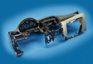
Ejection Forces

As depicted in china precision molds manufacturers, the item math and direction in the shape decides the number and area of the form’s splitting surfaces. In the event that the shape has no undermines or exceptional prerequisites, at that point just one splitting surface might be essential. In any case, in the event that the shape has inward or outer undermines, at that point extra splitting surfaces might be vital alongside the related discharge segments to impel the sliding cavity or potentially center additions to deliver the caught territories of the moldings so they might be catapulted. Such”split hole molds” are talked about in high precision mold factory.

The launch power, Feject, needed to eliminate a trim from a form center is an element of the typical power between the outside of the embellishment and the outside of the shape, Fnormal, along with the related draft point, φ, and the coefficient of static erosion, μs, between the formed part and the center addition. To appraise the discharge power, the contact power, Friction, is first figured as:

F friction=μs. Fnormal

The launch power is then determined as the segment of the rubbing power that is typical to the splitting surface:

Feject= cos(φ).Ffriction=μs .Cos(φ). Fnormal

The connections between these powers are spoken to in oem/odm automotives moulding factory. As the draft point diminishes from zero in Eq.11.2, the launch powers decline with the cosine of the draft point. The typical power acting between the formed part and the center is driven by the inside tractable anxieties in the plastic, which will make the plastic trim embrace the center like a versatile band. The ordinary power is assessed as the necessary of the lingering stresses, σ, in the formed part over the territory of the shaped part.

Estimated values for the coefficient of grinding shift from 0.3 for profoundly cleaned surfaces (with low surface unpleasantness) to more than 1.0 for harsh as well as finished surfaces [2]. Table 11.1 gives some coefficient of grating information produced by ASTM D 1894, Standard Test Method for Static and Kinetic Coefficients of Friction of Plastic Film and Sheeting. Prominently, grating materials, for example, filled PA6 have a higher coefficient of grinding. Surface completion is significant. In Table 11.1, LaserForm ST-100 alludes to a powdered, polymer-covered treated steel material that is molded into a green part with a laser and in this way sintered and penetrated with bronze to frame a thick, solid part with a 0.2 pμm surface harshness [3]. SL5170 is a fluid pitch material framed into a three-dimensional shape embed utilizing a stereolithography or polyjet measure with a surface unpleasantness of 3.6 pμm.

The obvious coefficient of erosion increments with surface harshness. The extremely high coefficient of rubbing equivalent to 5.47 among HDPE and SL5170 is accepted to be brought about by atomic bond [3].

The assessment of the remaining malleable burdens is an intricate capacity of the preparing conditions, form calculation, and material properties. A point by point treatment is well past the extent of china precision molds factory; chinese mold component machining manufacturers gives a decent proposal on the subject, and current PC reproductions can likewise give assessments of discharge powers [5, 6]. With the end goal of shape plan, traditionalist disentangling presumptions are applied to give a gauge of the launch power. The essential supposition that will be that the elastic anxieties in the embellishment are the aftereffect of the warm withdrawal of the cementing polymer inside shape. This presumption will make the examination over foresee the discharge powers since practically speaking the polymer (1) might be in a compressive state before the utilization of warm shrinkage, and (2) may will in general unwind. This article is from https://www.injectionmouldchina.com

Mould Injection and Ejection

High precision plastic injection mould manufacturers take it as common easy work to view a mold from external and seperated parts. An injection form has numerous structures to achieve the capacities required by the injection shaping procedure. Since there are a wide range of kinds of molds, the structure of a simple”two-plate” form is first examined. It is significant for the shape originator to know the names and elements of the form segments, since later parts will expect this information. The structure of these parts and more perplexing molds will be dissected and planned in ensuing sections. It’s an easy job for china molds produce services suppliers.


Another isometric perspective on the form is appeared, arranged on a level plane for activity with a flat injection shaping machine. In this delineation, the plastic liquefy has been infused and cooled in the shape, with the end goal that the moldings are currently prepared for discharge. To perform launch, the shape is opened by in any event the tallness of the moldings. At that point, the ejector plate and related pins are pushed ahead to push the moldings off the center. From this view, a large number of the shape parts are watched, including the”B”or center addition retainer plate, two diverse center supplements, feed framework, ejector pins, and guide pins and bushings. China standard components for injection mold have the high quality control about all these parts.


This demonstrates that the plastic embellishment comprises of two distinctive shaped parts (like a cup and a cover) connected to a feed framework. This form is known as a two-plate, cold-sprinter, 0r two hole family shape. The term”family form” alludes to a shape where numerous parts of changing shapes and additionally estimates are delivered simultaneously, most regularly to be utilized in an item get together. The term”two-cavity” alludes to the way that the form has two depressions to create two moldings in each trim cycle. Such multi-cavity molds are utilized to quickly and monetarily produce high amounts of shaped items. Molds with at least eight cavities are normal. The quantity of form holes is a basic structure choice that impacts the innovation, cost, size, and unpredictability of the shape; a cost estimation technique is given plan direction. Plastic precision injection mould manufacturers china are very competitive at all these points.

In a multi-cavity shape, the cavities are set over the splitting plane to give room between the form pits for the feed framework, c0oling lines, and different segments. It is commonly wanted to put the shape cavities as near one another as conceivable without yielding different capacities, for example, cooling, discharge, and so forth. To automotive molds made in china, this generally brings about a littler shape that isn’t 0nly more affordable, but at the same time is simpler for the disintegrate to deal with while being usable in all the more trim machines. The quantity of form cavities in a shape can be altogether expanded by utilizing a bigger shape, yet additionally by utilizing various sorts of molds, for example, a hot sprinter form, three-plate shape, or stack form as later talked about as for shape format plan.

This article is from https://www.injectionmouldchina.com.