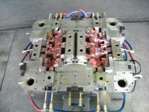
Klarm Mould Provides Precision Injection Molding

One normal technique for embodiment of fragile parts is pressure shaping as demonstrated in Fig. 13.6 for the creation of a tantalum capacitor. In this interaction, injection molding service china is set as a supplement between two layers of plastic 17 and 18 preceding the form conclusion. The shape configuration gives coordinating with pits 16 and 22 to get the plastic just as scores 21 to get the lead wires 20.

In any trim interaction, the form originator ought to expressly think about the treatment of the shaped parts upon de-embellishment. In the plan of Fig. 13.6, the lower cavity 22 is more profound than the upper depression 16. Furthermore, the lower shape half 11 is given a blaze well 23 for the assortment of any plastic that streams out of the depression during the pressure forming measure. Because of these plan components, the formed part will stay on the lower shape half when the mold opens.

In this pressure shaping interaction, the plastic layers 17 and 18 were cut from sheet stock in a structure to find a way into their comparing cavities while additionally supporting the capacitor 19 and lead wire, 20. It is attractive that the plastic completely contacts the back surface of the shape pits to work with heat move and plastic framing during china injection design service.

Preceding mold conclusion, cartridge radiators in the two form parts 10 and 11 bring the temperature of the shape and plastic layers to over the glass progress temperature of the plastic. When the plastic is mellowed, the shape is gradually shut with low power. As the form gradually shuts, the plastic gradually streams around the capacitor until it is completely epitomized – any abundance plastic in the hole will f1ow out the blaze surface, 24, and into the glimmer well, 23. When the embedded part is completely typified, full clasping power might be applied to the two form parts to make up for shrinkage and accomplish the ideal measurements while the shape is cooled.
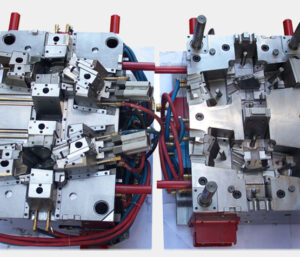
The shape plan of plastic precision injection mould factory has some interesting highlights. In the first place, the depressions secure the addition part in the form to stay away from undesired development brought about by the development of the shape or the progression of the plastic soften during the embellishment interaction. Second, this cycle was explicitly intended to give l0w weight on the embedded part by the controlled warming of the mold and relaxing of the plastic followed by the bracing and cooling of the shape. Given this warming and cooling cycle, the form ought to be painstakingly intended to limit the size and thickness of the plates s0 that energy utilization and process duration are limited. Third, this cycle utilized a lash surface and repository to control lashing of excess plastic; it is plainly attractive to choose a measure of plastic stock that limits the measure of lashing while at the same time guaranteeing a completely filled pit. In this plan, the mating lash surface, 24, on the lower form requires a moderately enormous leeway with mating surface on the upper shape half. In the event that this leeway is too little, the pace of the pressure shaping cycle can be restricted by the progression of the plastic dissolve out of the depression.

This is from https://www.injectionmouldchina.com/

Klarm Mould Offers Precision Molding Service

In the past model, the diversion of the side divider was not an issue. In any case, this issue would almost certainly be huge if the dissolve pressures were higher, the mold cavity was more profound, or the embellishment resistances were more tight. The mold creator from china mould produce services could increment the width of the cheek to decrease the side divider avoidance. In any case, this approach adds huge size and cost to the form. Another option is to use interlocks on the splitting plane close to the edges of the mold to move part of the bowing burden from the fixed portion of the mold to the moving portion of the mold.

Round and rectangular form interlocks are appeared in Fig. 12.20. The two sorts of interlocks ought to be put 0n the splitting plane and as near the form cavities as could be expected. When all is said in done, the rectangular interlock will give more noteworthy protection from diversion because of its bigger size and cross-sectional region across the interlock. However, round interlocks are accessible in more modest sizes and are simpler to introduce in a mold.

A detail perspective on a form configuration consolidating a round interlock is appeared in plastic precision injection mould factory. In this plan, the male interlock is found a way into a through opening in the B plate of the mold. The female interlock is found a way into a visually impaired pocket in the more profound A plate of the mold. The two interlocks firmly fit into the encompassing plates, and are held in the stature course with attachment head cap screws. It is significant that the mold deendorser doesn’t imperil the underlying respectability of the side divider by eliminating abundance mold material while joining the interlocks. At the point when the dissolve pressure is applied 0n the side divider, the interlock will move part of the heap from the A portion of the form to the B half of the mold. The utilization of the interlock adequately doubles the firmness of the side divider, bringing about a splitting of the measure of the side divider diversion.

Since bigger interlocks can convey higher burdens, the biggest interlock ought to be utilized that can be promptly consolidated into the mold plan. In the event that the interlock is presented to a sidelong power, Fateral, applied by the side divider, at that point the shear pressure in the between lock, Tinterlock, can be assessed as:

Tlnterlock= Flnteralock/Alnterlock

where Alnterlock is the cross-sectional region of the interlock at the splitting plane. In the event that the interlock is made of S7 device steel, the plan ought to give a shear pressure less than 300 MPa to stay away from disappointment. It ought to be noticed that temperature contrasts between the moving and fixed mold parts can cause misalignment of the between bolts and sped up wear during mold activity. Ordinary examination during mold support is suggested since this wear can lead straightforwardly to center movements and changes partially measurements.

Gauge the shear pressure in the 19 mm measurement interlock used to help the side mass of the cup cavity.

The essential vulnerability in this investigation is the assessment of the sidelong power applied to the interlock. This assessment of the sidelong power is confounded by the round state of the cup that gives a non-uniform cheek width between the guide pins. Be that as it may, a gauge can be given by accepting that the interlock is presented to the horizontal power from the close by surface of the mold pit. As demonstrated by the brought forth part of oem/odm industrial injection moulding design factory that represents the close by plastic, the powerful zone can be assessed as the item of the interlock width and the depression tallness.

Obviously, the interlock won’t be presented to the entirety of the horizontal power from the soften pressure applied as an afterthought mass of the mold cavity. A moderate gauge is that portion of the power will be conveyed by the interlock. This article is from www.injectionmouldchina.com

Final Shrinkage

The disastrous the truth is that to china mould manufacturing manufacturers, the specific shrinkage won’t be known before the shape is planned, manufactured, and tried. The objective in the setting up the last shrinkage proposal

■to give a shrinkage esteem that is near the real shrinkage of the material,

■to furnish a form machined with a shrinkage esteem that might be worked under a scope of cycle conditions to bring the part measurements inside particular, and

■to give a form that is machined”steel safe” with the end goal that the shape can be promptly adjusted if important to bring the part inside determinations.

The introduced shrinkage investigation should give sensible shrinkage gauges given legitimate dissolve temperatures and soften pressures. In any case of plastic injection moulded components china, the assessed contract age can differ broadly given vulnerability about material properties and handling conditions. Therefore, the shrinkage investigation ought to be considered as supplementing different wellsprings of data about shrinkage, The shrinkage examination ought not be utilized in disconnection given the potential for blunder. Notwithstanding, the shrinkage examination ought to be utilized to confirm the shrinkage gauges coming from different sources.

There are a few normal wellsprings of shrinkage information that might be utilized (notwithstanding examination) to help  plastic injection mold manufacturers china with setting up the last shrinkage proposal. Most ordinarily, a material provider or other testing research center may shape parts in a standard test form to assess the shrinkage. Commonly, the test form comprises of a 2 or 3 mm thick plaque that is shaped at mid-range dissolve temperatures and weights. The formed parts are then permitted to equilibrate for quite a while before their measurements are estimated and the straight shrinkage determined. This shrinkage data, when accessible, is generally precise since the testing was led for the specific material of interest at conditions near most embellishment applications. In any case, the gave shrinkage information may not be exact if the divider thickness or handling states of the embellishment application differ essentially from that of the test shape.

One critical issue with shrinkage information from a material provider is that the shrinkage information may not be founded on testing of the genuine material by high-precision molds made in china, but instead suppositions that the material will carry on as evidently comparative materials that have been recently tried. A more costly however more precise option is to configuration, assemble, and test a model shape that has a stream length, divider thickness, and cooling framework like the particular embellishment application. Such model embellishment gives dissolve weights and temperatures that ought to be fundamentally the same as those of the last creation form, so the shrinkage saw with the model shape should be near the last production form. While the advancement of a model shape can be costly, the exactness of the shrinkage estimations can be helpful in close resilience applications.

Another choice is to depend on shrinkage information from past form plans and decay insight. Much of the time, molds may as of now have been planned and worked for creation of moldings that are fundamentally the same as the current form plan application. In such cases, the mold originator of injection molding service china may acquire the best gauges by contrasting the estimations of the moldings and those of the shape steel measurements.

Before making last proposals, in any case, the shape originator ought to ask with the decay to check if the disintegrate would have liked to work the trim machine at various liquefy temperatures as well as weights. Provided that this is true, the form originator ought to ask the disintegrate to create moldings at the favored conditions (regardless of whether the moldings fall outside of determination), and afterward ascertain the shrinkage of these moldings for use in shape plan applications.

A fourth choice is to perform modern PC reenactment of the mold filling, pressing, and cooling stages to foresee the straight shrinkage in the trim application. While PC reproduction uses further developed material science and gives more definite outcomes than the shrinkage examination introduced here, the PC reenactment is as yet dependent upon similar mistakes with respect to the expected material conduct and preparing conditions. Nonetheless, the mathematical recreation can be important to approve the manual shrinkage examination while giving nonuniform shrinkage gauges over the shape pit.

In building up the last shrinkage suggestion, the form architect ought to play out the introduced shrinkage investigation and affirm the outcomes with information from the material provider and past experience, if accessible. On the off chance that the shrinkage rate is dubious, at that point the shape fashioner ought to discuss the expected blunder with the disintegrate, material provider, and end-client to diminish the vulnerability and survey obligation should the used shrinkage rates be so incorrect to bring about expensive form changes. In certain agreements, the last shrinkage proposal is the duty of the form’s client who eventually pays for the expense of the shape plan and any slip-ups. In different cases, no gathering might be happy to acknowledge duty regarding a questionable shrinkage rate, so the gatherings may concur that a model embellishment venture is important to portray the shrinkage and diminish hazard.

This article is from https://www.injectionmouldchina.com

Coolant Flow Rate

When the cooling time is known to the china injection mold maker, the warmth move rate or”cooling power” expected of the feed system of the double coler mold parts can be determined. The aggregate sum of warmth to be eliminated by the cooling framework, Q mlingsg, is:

where mmoldings is the com bined mass of the formed parts and any related cold sprinters, which can be assessed as the volume of these moldings times their thickness at room temperature.

The cooling power is the characterized as the measure of energy that the must be eliminated every second of cooling time:

Normally, an injection mold has numerous cooling lines. Expecting that the mold is all around planned and each cooling line renoves a similar measure of warmth, at that point the warmth move rate per cooling line might be assessed as:

where nuines is the all out number of cooling lines in the shape. Now, the oem/odm largest plastic injection molding companies ought to perceive that various plan cycles might be important to play out the cooling investigation for various cooling line formats with shifting number of cooling lines.

Any warmth eliminated from the polymer dissolve in the shape hole must be diverted by the coolant. In that capacity, the coolant will increment in temperature as it goes through the shape. This temperature increment isn’t alluring, since the coolant will give less cooling to the last segment of the form through which it streams, If the coolant temperature increment is excessively incredible, at that point warm slopes will emerge over the shaped part, which may prompt differential shrinkage and warpage.

Given a volumetric stream pace of the coolant, V2o the expansion in the coolant

coolant’ temperature along one cooling line is:

The warm properties of some normal coolants are given by plastic mould manufacturers factory. The necessary coolant stream rate can be determined given the permissible increment in the coolant temperature. A commonplace permissible increment in the coolant temperature is 1°C. For an exactness forming application, the permissible increment in the coolant temperature might be 0.1°C. A lot more tight control of the coolant temperature requires a lot higher stream rates, but gives little included advantage given that the form hole surface temperatures will in general change all the more fundamentally between the cooling lines as later talked about.

Subsequent to assessing the necessary coolant stream rate, the plausibility of this worth ought to be checked against the abilities of business form temperature regulators. The determination for an ordinary coolant temperature regulator and an oil temperature regulator are recorded in oem/odm medical mold design factory.

The admissible scope of cooling line distances across would now be able to be resolved dependent on the warmth move and liquid stream limitations. To guarantee satisfactory warmth move from the shape steel to the coolant, tempestuous stream in the coolant is wanted. In the event that the cooling line width is excessively enormous, at that point the direct speed of the water may not be adequate to guarantee violent stream. To guarantee violent stream, the Reynolds number, Re, ought to be more prominent than 4000.

An additionally restricting imperative administers the base cooling line breadth, which is identified with the weight drop needed to compel the coolant through the cooling lines at the necessary volumetric stream rate, The weight drop for water through a cooling line can be assessed from pipe stream.

To figure the base cooling line measurement, the line length and passable weight drop over the cooling line must be known. This data can really be somewhat questionable, since it depends not just upon the design of the cooling lines in the shape, yet additionally whether the cooling lines are funneled in arrangement or equal.

This article is from https://www.injectionmouldchina.com

Shear Rate

Simultaneous with deciding the gating location(s), the form originator from injection mould manufacturers in china should likewise decide the kind of gate(s$) to be planned. Frequently, the determination of a kind of entryway is evident once the gating areas are indicated. The essential factors that ought to be considered incorporate the sort of sprinter framework, the ideal strategy for de-gating, the permissible degree of shear rates through the entryway, and the subsequent stream that is wanted. To encourage entryway choice, Table 7.1 gives an outline of the sorts and properties of normal doors.

The de gating technique alludes to the utilization of the form activity to de entryway the parts, and doesn’t consider robotized de gating through mechanical technology. The expressed shear rate systems are inexact since they are a component of the entryway measurements and cycle conditions; the degrees of low, moderate, and high generally relate to shear rates on the request for 10, 40, and a 100,000 complementary seconds. At long last, most entryways bring about a spiral stream design out of the door with just the fan, glimmer, and stomach entryways deliberately intended to give straight liquefy stream into the form pit.

In choosing entryway areas and types, the utilization of blended hot and cold sprinters ought to likewise be thought of. Injection mold services china exhibits the utilization of a hot drop with a warm door that takes care of four sub-sprinters and parts masterminded in an outspread format. Such an arrangement could be utilized with a hot sprue bushing to spare material in an ordinary two-plate form, yet is very regular in the hot sprinter molds with an”X” complex setup. Such an application with the plan of Fig. 7.20 would bring about the creation of 16 holes with amazing material turnover in the hot sprinter, low weight drop from the trim machine, and productive material usage in the chilly sprinter.

The shear rates are determined by the recently given conditions to stream in strips and chambers. For reference, the formulae for Newtonian and force law streams are given in Table 7.2. These recipes depend on the volumetric stream rate as opposed to the direct dissolve speed. The explanation is that embellishment measures are arrangement with the volumetric stream rate being indicated, and that the straight dissolve speed of the polymer soften through the entryway isn’t promptly watched. Accordingly, shear rates in doors and sprinters are ordinarily determined as a component of volumetric stream rate.

High-quality double coler mold parts gives the material properties and suggested most extreme shear rates for certain materials. The greatest shear rates ought to be viewed as rough, best case scenario, since as a rule these qualities are taken from general rules for different materials. In all actuality, the greatest shear rates are reliant on the most extreme shear rate, yet additionally the whole warm and mechanical history of the polymer soften. In numerous if not most cases, a lot higher shear rates might be conceivable than the greatest shear rates recorded in Appendix A. Given this problem and the simplicity of expanding the size of entryways, it might be alluring for the shape planner to be”steel safe” and indicate a littler door with the expectation that the form will be tried and the door sizes expanded as important to keep away from inordinate shear rates and tweak the stream.

To ascertain the shear rates, the shape creator must determine some underlying door measurements. For thicker doors having low and moderate shear rates (counting the sprue, edge, tab, fan, and valve entryways), the underlying thickness might be set equivalent to the divider thickness of the embellishment at the location of the entryway. For more slender entryways having moderate and high shear rates (counting the pin-point, streak, stomach, passage, submarine, and warm doors), the underlying thickness might be set equivalent to one a large portion of the divider thickness of the embellishment. Strip-type doors likewise require the detail of the width. For blaze and stomach entryways, the width ought to be set to the edge length along which straight stream is wanted. For other strip-type entryways, the underlying width might be set to double the door thickness; this width can be expanded or diminished to modify the shear rates as vital.

This article is from https://www.injectionmouldchina.com.

Tunnel

Except for the pin-point entryway utilized with a three-plate mold, all the first gates designs from china mould design services require the expulsion of the feed system from the trim by some post-forming framework (as a rule the administrator). The passage entryway is a typical kind of gate that can be viewed as a variation of the pin-point door. Its essential bit of leeway is that the passage entryway pr0vides for programmed de-gating with the activation of a basic two-plate shape. The plan of a passage entryway for the cover shaping is appeared. Contrasted with the pin point entryway, the progressions have all the earmarks of being corrective with the expansion of certain turns and tightens. These distinctions are irrelevant as for the progression of the plastic dissolve, so the components of the passage entryway ought to be resolved as recently examined to accommodate sensible shear rates and weight drops.

From the outset, the passage gate appears to be fundamentally the same as the pin-point entryway. Nonetheless, they vary altogether in structure and capacity. The capacity of the passage gate can be perceived by looking at the form plan. A cross area through the shut shape with the passage entryway is appeared. The way in to the capacity of the passage entryway is that the passage gate”tunnels” through the pit embed. The embellishment will move away from the depression supplement and remain on the center with the passage door when the shape opens. Simultaneously, the kickoff of the mold powers the passage part of the runner to incidentally stay with the cavity embed. The movement of the center supplement away from the hole embed causes the passage gate to break at its intersection with the embellishment. The embellishment and the feed system would then be able to be launched out as in an ordinary infusion forming measure.

The breadth of the passage entryway at the hole ought to be intended to stay away from unreasonable shear rates and weight drops. For the passage entryway to work dependably, there are two significant points that must be indicated. Initial, an ostensible 45 degree point ought to be kept up between the centerline of the passage door and the splitting plane to take into consideration the transmission of shearing worries to the entryway. Second, the passage door ought to have an included shape point of 20 degrees t0 guarantee that the passage entryway doesn’t stick in the form and that the passage entryway breaks at the intersection with the trim. To guarantee satisfactory auxiliary respectability of the pit undercut, the passage gate ought to be situated in any event three passage measurements off the splitting plane.

The passage gate is a sharp plan since it accommodates programmed de gating without huge venture. The essential danger in application is that the passage entryway might be inappropriately planned or wear with the end goal that lhe runner system doesn’t dependably degate from the trim. T0 help the de-gating of the passage gate from the formed part, the runners ought to be planned with close by sucker pins, to hold the runner system on the center side. In the event that the passage entryways and the runner system stay on the hole side, at that point they can’t be taken out through activation of the discharge system.

There are a few varieties of the passage entryway for the high-precision molds made in china. Similarly as the passage entryway burtows up into the hole embed, the term”submarine”gate alludes to a plan variation where the passage door slides into the center supplements. The activation of the ejector system and the launch of the embellishment of the center at that point demonstration to break the entryway and strip the feed system from the trim. With both passage and submarine entryways, it is likewise conceivable to configuration expanded gates that bend around vertical side dividers to gate onto the inside surfaces of the part. Such an all-inclusive submarine door configuration, otherwise called a”banana”or”cashew”gate,, however such plans represent extra danger as for solid de-gating.

This article is from https://www.injectionmouldchina.com

Hot Runner Section

This mold plan methodology of china precision mould manufactory diminishes the measure of machining as well as decreases the plan time and potential for machining or misalignment botches related with coordinating the two sides of a full round runner.

The essential downside related with these non-circular runners from injection mold maker china is that they offer ascent to nonuniform shear rates and shear worries over their cr0SS-segment. For instance, the trapezoidal runner is anything but difficult to machine, however the areas close to the four corners lead almost no stream down the length of the runner, The exhibition of the trapezoidal runner can be improved by adjusting the base surface to kill two of the corners. Notwithstanding, everything these non-circular sorts of runners will require to be marginally bigger and devour extra material to give a similar weight drop as a full round runner.

The recently depicted investigation can be adjusted for use with non-circular runner areas. While the outcomes won’t be as exact concerning a full-round runner, the water driven measurement, Dn, for every runner type can be determined where A section is the cross-sectional territory of the runner and Psection is the border of the crosS-segment of the runner. F0r reference, Table 6.3 gives conditions relating the predefined measurements to the water driven breadth. It ought to be noticed that the conditions in Table 6.3 have been determined accepting a 5 degree tighten point to help with the launch of the runner from the shape. This suspicion takes into account a decrease in the quantity of plan factors.

There is one other runner area that is very basic in hot runner frameworks: the annulus. In particular, numerous hot runner frameworks join valve pins down the length of the spouts to truly close off the entryway as along these lines talked about . In this plan, the polymer liquefy streams between a tube shaped drop and the round and hollow valve pin, framing an annulus.

The polymer liquefy move through an annular area might be firmly approximated by adjusting the condition for gooey stream in a strip. In particular, the width of the strip can be supplanted by the boundary of the mean breadth of the liquefy annulus, while the thickness of the strip is supplanted by the separation between the valve pin and the spout bore. Making these substitutions in Eq. 5.17 outcomes in the accompanying connection between pressure drop and stream rate in an annular segment for a Newtonian liquid. Where Dpin is the breadth of the valve pin and Dbore is the measurement of the drag through the spout. The force law model for an annulus can be correspondingly determined.

One model from high precision molds made in china is to figure the weight drop through a valve-gated spout having a length of 150 mm, a drag width of 10 mm, and a valve pin distance across of 5 mm. Expect a material with a thickness of 100 Pa-s streaming at a pace of 50 cc/s. Subbing these qualities into Eq. 6. 14, the assessed pressure drop. Another model: The essential runner in the three plate shape of Fig. 6.7 has a trapezoidal area. Compute the weight drop through a 120 mm length of essential runner with a width of 6 mm, a profundity of 8 mm, and a 5 degree tighten point. Expect the utilization of ABS with a stream pace of 44 cc/s.

This article is from https://www.injectionmouldchina.com

Mold Surface Treatment

While determining the material for different form segments, the mold originator ought to likewise think about the consistency of the stock material just as its capacity to be done and treated. Most metals are projected and therefore rolled/framed/cut to their provided mold. The subsequent grain structure and properties are an unpredictable capacity of the constitutive alloying components as well as the warm and auxiliary history during handling. Form creators, mold producers, and end-clients ought to know that there are numerous issues, for example, porosity (voids), contaminants, inhomogeneity, and leftover pressure that may affect the nature of the machined mold.

Consequently, it is suggested that the mold segments be machined from strengthened or standardized steel with negligible lingering pressure and uniform properties. These medicines can accommodate lower hardness and quicker machining. After the mold has been machined and completed by injection moulding china company, the completed part / injection molded parts china may again be toughened to confirm dimensional stabillity and afterward carburized (otherwise called case solidifying) to improve surface hardness by expanding the carbon content at the that are accessible including nitriding, boriding, plating, fume testimony, anodizing, and others. Here gives a correlation of a few surface medicines that might be chosen for explicit application-explicit purposes including expanded hardness, decreased coefficient of contact (COF), hardness, improved consumption opposition, and others.

In many applications, mold creators of injection molding service china will re-appropriate the mold segments to be treated by specialist co-ops that have practical experience in surface medicines. These medicines will expand the underlying buy cost of the mold yet can significantly build the life span and diminish related support costs, particularly when preparing grating saps or long creation runs. Disintegrates likewise frequently depend on surface medicines to determine issues, for example, improving lubricity of form surfaces to ease part discharge, diminish wear between sliding segments, fix scratches, or improve the outside of welded areas. Dissemination measures (e. g., carburizing, nitriding) don’t develop the thickness of the mold surface instead of coatings, which may include considerable mass.

Form architects and mold creators should observe the thickness and consistency of the applied covering, so pit divider thicknesses are intended to give a recompense to its thickness as suitable. Luckily, numerous coatings might be stripped and reapplied if fix or changes in surface properties are required.

The fomold format configuration measure incorporates the assessment of the part calculation to be molded to distinguish the splitting line, separating plane, and shut-offs. The center and hole embeds are then measured and found comparative with one another. A short time later, an appropriate form base is picked or planned that can effectively hold and backing the center and depression embeds. The mold format measure gets done with the choice of the materials utilized for the mold base just as the center and hole embeds. In many high precision plastic making mould china, these materials are promptly requested simultaneously with the nitty gritty investigation and plan of the form subsystems.

We gives a mold structure agenda to elite, standard, and fundamental mold; the subtleties are introduced. The following section looks at the mold pit filling measure, which is needed to 1) confirm that the part configuration can be created at accessible liquefy weights, and 2) gauge the stacking that will be put on the form segments. A short time later, the investigation and structure of the feed framework will be tended to.

This article is from https://www.injectionmouldchina.com/
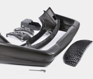
Mold Opening Rules

During the form format stage, the mold creator /injection molding service china affirms the kind of form and decides the measurements and materials for the depression embeds, center embeds, and form base. Form bases are just accessible in discrete sizes, so emphasis between the additions’ estimating and mold base choice is typical. The objective of the mold format configuration stage is to build up the physical components of the additions and mold to start obtainment of these materials. Mold material choice is additionally a significant choice, since the material properties to a great extent decide the form setting aside a few minutes and cost just as the form’s basic and warm presentation.

The mold format configuration accept that the quantity of mold holes and sort of mold has been resolved. For high precision plastic injection mould suppliers to build up the mold format, the mold opening course and the area of the splitting plane are first decided. At that point, the length, width, and tallness of the center and hole embeds are picked. Subsequently, a mold base is chosen and the additions are put in as basic and smaller a design as could be expected under the circumstances. It is imperative to build up a decent mold format plan since later investigation and itemized configuration accept the format structure, and resulting changes to the pit and form measurements can immediately get troublesome and costly.

The splitting plane is the contact surface between the fixed and moving sides of the mold. The basic role of the splitting plane is to firmly seal the cavity of the mold and forestall liquefy spillage. This seal is kept up through the utilization of actually huge amounts of power (consequently the term”clamp weight”) that are applied typical to the splitting plane. While the term”parting plane”implies a level or planar surface, the splitting plane may contain out: of plane highlights. Preceding deciding the splitting line and planning the splitting plane, the mold originator should initially decide the form opening course.

Injection mold maker china assessment of any of the past mold structures shows that the mold opening heading is typical to the splitting plane. Actually, the form generally opens toward a path typical to the splitting plane since the moving platen of the embellishment machine is guided by attach bars or rails to open toward a path ordinary to the platen. In like manner, control bushings or potentially mold interlocks are quite often situated on the splitting plane to manage the form opening toward a path typical to the splitting plane.

It might give the idea that there is nothing about the mold opening direction to decide since the mold opens typical to the splitting plane. Notwithstanding, it is important to decide the mold opening course comparative with the form pit and heading of part launch. There are two factors that administer the mold opening heading.

To begin with, the mold pit ought to be situated to such an extent that it doesn’t apply unjustifiable weight on the infusion mold. The form cavity is ordinarily positioned with its biggest region corresponding to the splitting plane. This plan permits the form plates, previously being held in pressure under the brace weight, to oppose the power applied by the plastic on the surfaces of the mold hole.

Second, the form hole ought to be situated with the end goal that the molded part can be launched out from the mold. A common formed part is molded like a five – sided open box with the side dividers, ribs, supervisors, and different highlights ordinary to its biggest region. Assuming this is the case, at that point the part discharge prerequisite again bolsters the form opening course to be typical to the part’s biggest extended territory.

Consider the cup and top appeared of the center and cavity embeds used to mold these parts was already. There are just two potential form opening directions comparative with the part. One mold opening heading is in the hub course of the cup, while the subsequent bearing is the spiral way of the cup.

The two striking flat lines demonstrate the area of the splitting plane where the two parts of the addition are part to frame the hole embed (top) and the center supplement (base).

Consider next a similar depression square yet with an outspread form opening course for a bit of the hole embed. For this plan, four striking lines separate the sides from the top and base. Since the metal Core is situated inside the molded part, there is n0 approach to rem0ve the center other than in the part’s hub bearing. The pit embed, in any case, can be isolated into three pieces that move along two unique tomahawks so as to eliminate the molded part.

Of these two structures, the hub mold opening bearing is the least complex plan and is normally liked. Notwithstanding, the subsequent structure is now and then utilized practically speaking since it takes into account a more intricate part configuration just as more alternatives in finding the splitting line. For example, the subsequent structure may be required if a handle were added to the cup or on the off chance that it were important to move the splitting line to an area away from the top lip. This subsequent structure is known as a”split depression mold” and is talked about in more detail.

As another model, think about the PC bezel. There are again two potential mold opening headings. The main opening course is in the screen’s review heading, as shown by the segment see. For this situation, the mold area is part by two level lines into a hole embed framing the external surface of the bezel and a center supplement that molds the internal surface and ribs of the bezel. At the point when the center and cavity embeds are isolated as demonstrated by the bolts, the formed bezel can be promptly taken out.

Then again, the depression hinder for the tablet bezel can be part as demonstrated with the three vertical lines. For this situation, the previous pit embed is part into two pieces, coming about again in a split hole mold plan. The two parts of the previous depression embed should now be taken out in sideways ways so as to eliminate the molded part; the form opening course is slanted so as to permit the mold surfaces to isolate from the molded part without inordinate surface rubbing or shearing of highlights on the molded part. This development requires a few extra mold parts to control the moving depression embeds, which add essentially to the expense of form configuration, production, and activity.

This article is from www.injectionmouldchina.com.

Prototyping Cost Assessment in Mould Manufacturing

The prototyping cost assessment strategies were principally created for class 101 injection molds that are proposed by injection molding service china for large scale manufacturing of a great many shaped parts. In numerous applications, there is the need to create form tooling for lower creation volumes or to”bridge” model and creation. For some embellishment applications, the four normal assembling techniques are:

  1. Class 101 creation molds,
  2. Aluminum tooling for moderate volumes,
  3. Model molds made by added substance fabricating with photopolymers of direct metal laser sintering.
  4. Items straightforwardly made by 3D printing through intertwined statement demonstrating, laser sintering, or stereolithography. For every system, the forthright cost, peripheral expense, and absolute creation time as assessed can be a component of various objective creation volumes as an update to earlier work.

Cost assessment by injection mould manufacturers in china is a settled cycle where the genuine costs needed to secure a made item are completely accounted. The exactness of a quote will change dependent fair and square of detail taken in representing all the exercises and costs in assembling, just as the accuracy of the related occasions and expenses.

Once more, the standard structure for the all out creation cost, C, is applied for every one of the elective assembling procedures. The all out creation time can be likewise determined as where tinitial is the underlying lead time to get the initial segment, and tmarginal is the creation time for each extra part. The normal part cost may likewise be assessed .

Two critical issues in the assessment of shape prototyping techniques are (1) the nature of the secured parts and (2) the life span of the model tooling. To start with, model shape infrequently give the surface completion and execution of parts formed from creation tooling. Specifically, 3D printing measures have a limited goal or line width that can bring about unpleasant surfaces that limit the part style and execution. Straightforwardly created parts (by FDM, particular laser sintering, or stereolithography) have a diminished arrangement of evaluations just as fairly substandard properties identified with the trustworthiness of the established materials. Second, model tooling can have a shorter lifetime because of stress-related disappointments related with infusion of the polymer soften or potentially ejection of the shaped plastic parts.

Hence, it is critical to create sensible expense and time gauges for each assembling methodology by china high-precision mould suppliers. It gives some firm quotes to elective methodologies for creation of the shaped bezels. The initial two lines compare to the two-cavity hot sprinter and one cavity cold sprinter shape that were recently dissected. An option is the utilization of printed embeds that were delivered by a poly jet cycle with bright restored sap. This kind of shape embed has a lifetime on the request for 100 trim cycles, so the form embeds must be consistently recreated to accomplish high creation amounts, which prompts a generally high negligible creation cost of $33 and peripheral creation season of 1 h. Then again, the bezels might be legitimately delivered by melded testimony demonstrating or particular laser sintering with a minimal expense of $60 and a minor creation season of 4 h.

This article is from https://www.injectionmouldchina.com/.