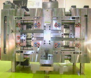
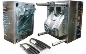
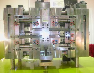
The mold configuration should likewise incorporate clasp to inflexibly attach the numerous parts of the form. There are three sorts of latches generally utilized in molds while injection moulding china.
In the first place, fits are utilized by oem/odm industrial injection moulding design factory to firmly find one segment inside another, for example, a pit or center addition being situated inside a retainer plate. Second, finding pins or dowels are utilized by chinese injection moulding companies to find one parts over another, for example, the ejector lodging to the help plate. These initial two attaching strategies just give securing across the length and width headings of the mold. To attach the mold parts together in the tallness bearing, attachment head cap screws are utilized wherein the screw’s head is held in a form plate and the screw’s strings draw in the segment to be affixed. Every one of these attaching techniques is next broke down.

A”fit”refers to the mating of two segments. A leeway fit alludes to a mating where an ostensible freedom between the surfaces of the two segments. While a leeway fit furnishes for simple get together with insignificant inclusion powers, the freedom between the two segments allows the exact area of segments to stay obscure. Since tight resistances are needed in molds, impedance fits are normally used to find the mold segments.
Obstruction fits happen when the male segment has an ostensible measurement that is bigger than the ostensible element of the female segment, as demonstrated in injection moulding services for a center addition and a retainer plate. Since metals have a high versatile modulus, an inflexible obstruction fit can result when the distinction between the ostensible measurements is little, on the request for 0.01 % of the ostensible measurement. The snugness and inflexibility of the obstruction fit increments with the measure of impedance between the two segments. Sadly, the execution of obstruction fits is blocked by the dimensional varieties forced in the segments machining measures. Therefore, standard systems of fits have been created as far as possible on the elements of the segments.
The fits investigated here depend on a one-sided opening premise and have been changed over from U.S. standard units to metric units. Two of the most widely recognized principles for fitting include”Preferred Limits and Fits for Cylindrical Parts,” ANSI B4.1-1967 (R1999), and”Preferred Metric Limits and Fits” ANSI B4.2-1978 (R1999). ANSI B4.1 is investigated here because of its general straightforwardness and expansive materialness, however the mold originator may adjust to whatever standard is generally fitting. In this strategy, rectangular individuals with width, W, and length, L, are demonstrated as a roundabout part with clear distance across, D.
where C is a coefficient relating to the lower and furthest cutoff for the male or female segment given by worldwide norms. Table 12.1 gives coefficients to locational-obstruction fits (LN1 to LN3) and drive-impedance fits (FN1 to FN3). Locational-impedance fits are utilized when the exactness of area is basic and the parts require sidelong unbending nature. Be that as it may, locational-obstruction fits don’t give huge maintenance power in the stature course, so the parts should be gotten in the tallness heading to another segment through screws or different methods. FN1 to FN3 compare to drive fits with expanding impedance and requiring expanding addition powers. While drive fits give semi perpetual gatherings, mold plans for the most part give screws or different intends to decidedly holding the segments in the tallness heading.
This article is from https://www.injectionmouldchina.com/

