Attachment head cap screws are the most well-known latches utilized in molds. A %”13 attachment head cap screw is appeared in Fig. 12.32. The essential explanation is that attachment head cap screws have been deliberately planned [12] to enhance the exhibition of the head, strings, and fastener as a framework. In like manner, the attachment head cap screw gives a norm and efficient technique for holding numerous parts along the screw’s hub in injection mould tooling china.
The sizes and burden conveying capacity of attachment head cap screws are identified with their size, material, and medicines. Investigation of standard attachment head screw plans demonstrates that the head tallness is equivalent to the string width, and that the head distance across is around 150% of the string breadth. While the strength of the latch changes to some degree with the coarseness of the string, the rigidity of standard DIN/ISO screws can be genuinely very much assessed by accepting an extreme pressure, ultimate, of 800 MPa duplicated by the cross-sectional zone of the external string width.
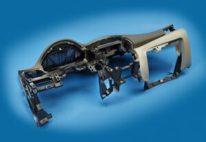
Indicate the size of the attachment head cap screws used to secure the fixed and moving parts of the PC bezel mold. Since this attachment head cap screw is utilized in a basic application of high-precision mould china where disappointment may bring about loss of gear or life, a most dire outcome imaginable is expected.
To begin with, the most extreme mass of the form is assessed accepting a strong square of steel as indicated by the measurements gave in Fig. 12.7.
Then, the most dire outcome imaginable is expected. The most dire outcome imaginable happens when the shape is braced to just one side of the trim machine without the help of the moving platen, which may happen when the form is being introduced in the embellishment machine. Besides, the most dire outcome imaginable will expect that the whole mass of the shape should be upheld by just one fixed screw, which may happen if the other cap screws are not fixed or fixed to lesser sums. The subsequent burden case is appeared in Fig. 12.33.
The applied power on the screw by the form can be assessed by adding the minutes about the finding ring.
Cap screws ought not be depended upon to find form segments given their moderately huge spiral clearances. As recently examined, an obstruction fit ought to be utilized to find one part inside the pocket of another. For equal plates or stacked parts, in any case, dowels or other finding pins ought to be utilized as demonstrated in Fig. 12.34. In this plan, concentric openings are given into the coplanar surfaces of the two plates. A dowel at that point mates with the two openings to find the two parts along the pivot of the dowel.
Assembling differences in the openings’ area, width, and roundness limit the capacity to exactly find the two parts comparative with one another. Condition 12.28 can be utilized for different sorts of fits by fluctuating the cutoff cofficients, C, for the dowel and openings as per global guidelines. Table 1 2.2 gives Coefficients to a locational-leeway fit (LC1), locational-momentary fits (LT1 and LT3), just as the loosest locational-impedance fit (LN1). Locational freedom fits are planned for parts that are commonly fixed yet can be promptly dismantled and reassembled. This fit gives similar request of resistance as strung latches, so isn’t suggested for injection molds since the huge freedom can permit sped up wear of sliding surfaces. Locational-progress fits accommodate more tight control of area, yet with the chance of impedance between the dowel and the opening which upsets the shape get together.
This article is from https://www.injectionmouldchina.com
