Shrinkage Analysis

As a rule, for high precision plastic injection mould suppliers, inadmissible nonuniform shrinkage isn’t perceived until after the shape is planned, manufactured, and tried. At times, the expansion of sprinters and entryways might be a moderately basic and cheap action. In different cases, nonetheless, the expansion of two doors may end up being costly, with negative repercussions on weave line areas and feel. For instance, the alteration from a two-drop “straight bar”” complex to a four-drop “H”or”X” style complex may require the buying of another complex, the expansion of bores to the A-side of the form, and the re-directing of cooling lines. By and large, the form planner and disintegrate will initially attempt to address the shrinkage conduct through preparing or material changes as portrayed in  oem/odm automotives mold factory.

For approval of the portrayed shrinkage examination, economically accessible soften temperature and weight sensors were stacked to supplant ejector pins in a form for creation of 3.2 mm thick, ASTM pliable bars [9]. As appeared in OEM/odm medical injection moulding design factory, every infrared dissolve temperature sensor (Futaba EPSSZL) supplanted an ejector pin that heaps a soften pressure sensor (Futaba SSB1KN) situated inside the ejector retainer plate. The weight applied by the polymer liquefy to the uncovered surface of the temperature sensor gave a push power to the dissolve pressure sensor.

A Design of Experiments (DOE) was executed as appeared in Table 10.1 for trim the test examples of polypropylene. The 18-run configuration is full factorial as for 3 degrees of pack weight and 3 degrees of slam speed. The form coolant and barrel temperatures were hindered to rehash the full factorial plan at low and significant levels of temperature.
Figure 10.11 plots the obtained soften temperature signal close to the entryway for the primary pattern of every one of the DOE runs; the striking follow relates to run 14. The temperature signal starts close to the form coolant temperature. As the polymer liquefy passes the sensor, the temperature moves to a level close to the barrel temperature. The detected dissolve temperature fluctuates with the barrel temperature and infusion speed settings. There is an outstanding rot in the detected soften temperature as the warmth is directed to the cooler shape as per the investigation of Eq, 9.4. There is a later deferral in the cooling somewhere in the range of 20 and 25 s, likely because of inert warmth of combination as the polymer sets.

Figure 10.12 plots the depression pressure close to the door for similar cycles plotted in china precision plastic injection die manufacturers. The nature of the signs is incredible considering the utilization of the temperature sensor as a heap transmission medium. The impact of the three pack pressure settings is obviously noticed comparing to top depression pressures around 25, 50, and 75 MPa. A slight counterbalance in the hour of the pinnacle soften pressure is seen which compares to the adjustments in the infusion speed. The barrel and coolant temperature settings influence the pinnacle pit pressure just as pace of rot during pressing.

The particular volume of the polymer is plotted in high precision plastic injection mould manufacturers for run 14 of the DOE utilizing the weight volume temperature (PvT) shrinkage model of china industrial injection moulding manufacturers. During the embellishment cycle, the warmed polymer changes from semicrystalline strong to shapeless liquid around 170°C. During flling and pressing, expanded weight packs the dissolve thus lessens the particular volume. The particular volume at that point diminishes as the polymer in the pit encounters further pressing/cooling.

This article is from https://www.injectionmouldchina.com
Three Plate Mold

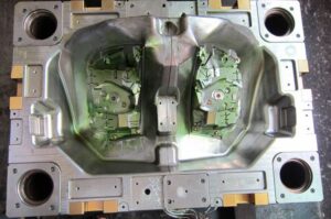
A separated isometric perspective on a completely open three plate mold configuration is given; the view gave does exclude the ejector lodging and related parts, since these are not key to the activity of the three-plate mold. Three-plate molds, the high precision molds made in china are contained three mold areas that move comparative with one another, with each segment comprising of one 0r more plates. The expansion of a subsequent splitting plane between the A plate and the top clip plate takes into consideration sprinters to be situated over the mold cavities and to cross across the width and length of the splitting plane without meddling with the mold holes. Thus, the three-plate mold gives more noteworthy opportunity regard to gating areas and the feed framework mold. An additional advantage is that three-plate mold of high precision plastic injection mould suppliers regularly give programmed partition of the molded parts from the feed system.

China industrial injection mold suppliers give a part through a completely shut three-plate mold. In this plan, the polymer soften streams down the sprue bushing over the thickness of the top clip plate and stripper (or”X”) plate. The polymer dissolve at that point streams along sprinters situated in the splitting plane (alluded to here as the”A-X”parting plane) between the A plate and the stripper plate. Tightened sprues are then used to pass on the soften through the thickness of the A plate and any cavity embed uphold plate t0 the mold holes.

Sprue pullers, likewise known as”sucker pins,” are utilized close to the sprue areas and different bits of the sprinter to guarantee that the feed framework stays with the stripper plate; the mold architect should plan the sucker pins with the end goal that they don’t limit stream. In the feed framework plan, the pins have a little breadth and profundity contrasted with the elements of the essential sprinter. To additionally diminish the stream impediment in the plan of Fig. 6.8, they could be moved further away from sprue bushing.

Mould produce factory gives a segment through a halfway opened three plate mold. Subsequent to trim, the B side of the mold is pulled away from the A side, driving the mold to open at the splitting plane between the An and B plates; the ejector framework, back brace plate, and related parts have been discarded. A spring situated between the A plate and the stripper plate might be utilized to cause early partition of the A-X separating plane. The B side keeps on opening, with the separation between the A and the B plates constrained by the length of a stripper jolt interfacing the A plate to the B plate. The free length of the stripper jolt must be adequate to consider the launch of the molded parts. A run of the mill mold opening separation between the An and B plates is equivalent to two to multiple times the tallness of the molded parts. This separation can be very enormous for molded parts with even moderately shallow centers.

When the length of the stripper jolt is crossed, the A plate will move away from the fixed platen alongside the B plate. The A plate will cross the free length of the stripper jolt for the stripper plate. The free length of this stripper jolt decides the mold opening separation between the A plate and the stripper plate.

Likewise with the A plate stripper jolt, the length of the X plate stripper jolt must be adequate to take into account the expulsion of the feed framework. When the A plate crosses past the free length of the X plate stripper jolt, the stripper plate will move away from the top brace plate alongside the A segment, B segment, and discharge arrangement of the mold.

It gives a segment through a completely opened three plate mold without the ejector system or back clasp plate. During mold activity, the mold opening speed and position must be deliberately decided and controlled to accomplish a productive and completely programmed cycle. On the off chance that the mold opening measurements are not painstakingly determined, at that point the feed framework may not be dependably shot out or the mold can be harmed. To advance the mold activity, the mold opening separations in numerous three-plate molds can be balanced by changing the situation of nuts on the stripper screws or by including washers between the plates and the finishes of the stripper fasteners.

It ought to be noticed that this three plate configuration has been made as minimized as conceivable as for mold opening separations, determination of plate thicknesses, and stripper jolt lengths. Accordingly, it is quick to analyze the plan of the three-plate mold with that of the two-plate mold. The extra plates and parts in the three-plate mold have expanded the stack stature by 44 mm (134 inches) and the mass by 30 kg, moderately little increments (on the request for 20 %). Nonetheless, the three-plate mold has a mold opening separation of 250 mm, a lot more noteworthy than the mold opening separation of 75 mm for the two-plate mold.

This bigger mold opening separation is unwanted, since it adds to the mold opening and shutting time and may likewise keep the mold from working in some infusion molding machines with restricted light.

This article is from https://www.injectionmouldchina.com/